G-116 Safety Sensors / Components
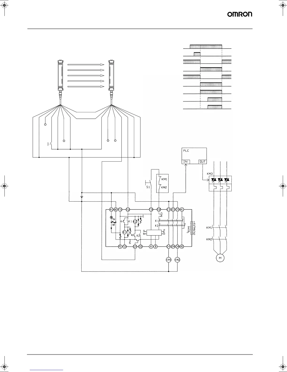
G9SA-301 (24 VAC/VDC) with 2-channel Safety Area Sensor/Manual-reset
KM3
E1
Feedback loop
Reset switch S1
Timing Chart
PC input
PC output
Emitter Receiver
F3SN-A
F3SH-A
KM3
Open
Open
Control
circuit
F3SN-A Incident
Interrupted
K1 and K2
(NC)
K1 and K2
(NO)
KM1 and KM2
(NC)
KM1 and KM2
(NO)
F3SN-A: Safety area sensor
S1: Reset switch
KM1 and KM2: Magnetic Contactor
KM3: Solid-state Contactor
M: 3-phase motor
E1: 24-VDC Power Supply
Note: This circuit achieves EN954-1
Safety Category 4.
Shield
0V (Blue)
OSSD2 (White)
OSSD1 (Green)
Auxiliary (Yellow)
EDM input (Red)
+24V (Brown)
+24V (Brown)
Open
Interlock selection
input (White)
Reset input (Yellow)
Test input (Green)
Open
(Red)
0V (Blue)
Shield
RS-485(A) (Gray)
RS-485(B) (Pink)
F502-EN2-04.book Seite 116 Dienstag, 26. Juli 2005 5:48 17

 Loading...


