EasyManuals Logo

Omron G9SA Datasheet

Omron G9SA
14 pages
To Next Page IconTo Next Page
To Previous Page IconTo Previous Page
Page #9 background imageLoading...
Page #9 background image
G-117G9SA
G9SA
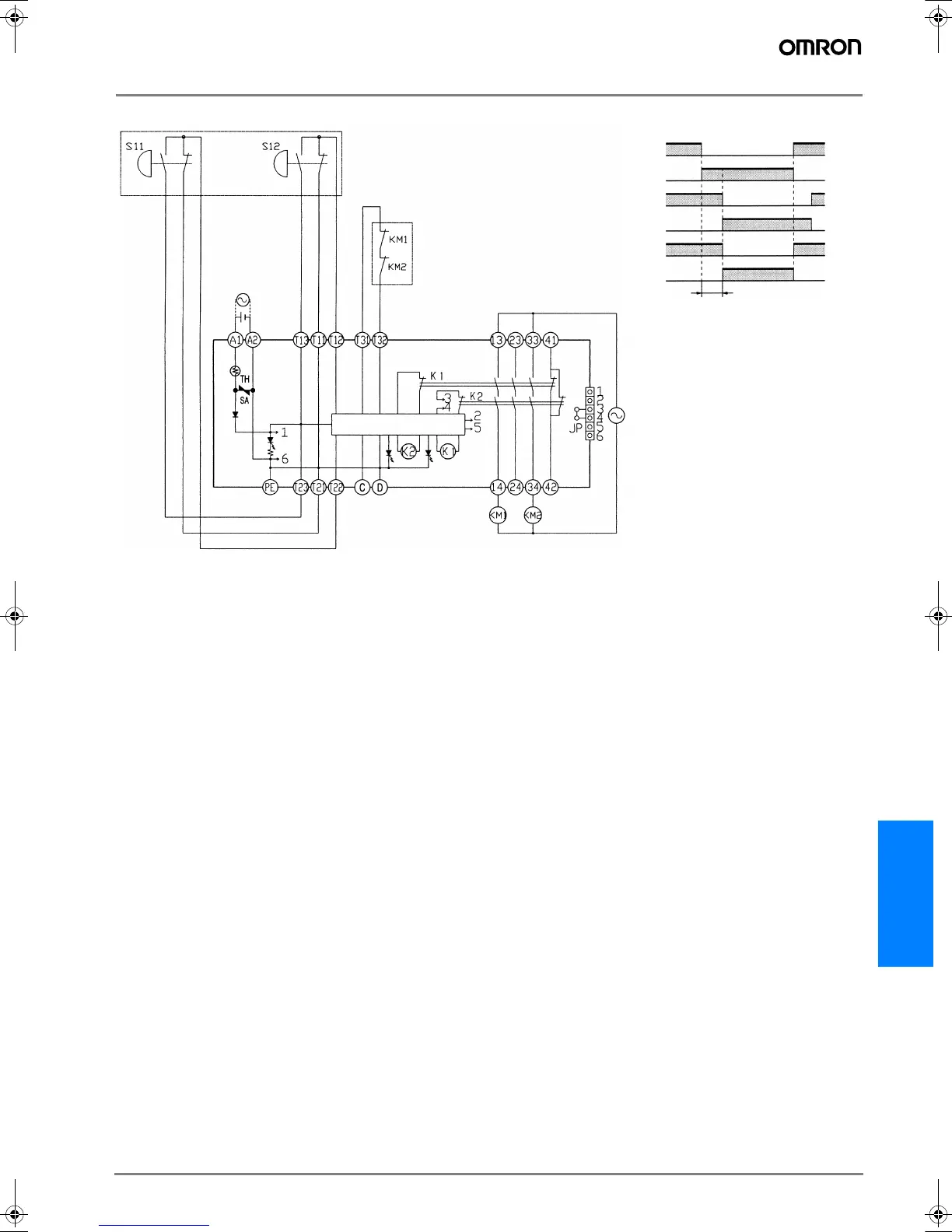
G9SA-TH301 (24 VDC) with 2-hand Inputs/Auto-reset
Feedback loop
S11 (NC)
S11 (NO)
Timing Chart
S12 (NC)
S12 (NO)
0.5 s max.
Control circuit
KM1 and KM2
(NC)
KM1 and KM2
(NO)
Input time difference operates only
when the difference is 0.5 s max.
S11, S12: Two-hand pushbutton switches
KM1 and KM2: Magnetic Contactor
Note: 1. Use a 1NC+1NO switch for S11
and S12.
2. This circuit achieves EN954-1
Safety Category 4.
(See note 1.)
Typ III C (EN 574)
F502-EN2-04.book Seite 117 Dienstag, 26. Juli 2005 5:48 17

Other manuals for Omron G9SA

Questions and Answers:

Question and Answer IconNeed help?

Do you have a question about the Omron G9SA and is the answer not in the manual?

Omron G9SA Specifications

General IconGeneral
Rated Current6A
Mounting TypeDIN Rail
Dimensions90mm x 22.5mm x 100mm
WeightApprox. 200g
Safety CategoryCategory 4
Rated Voltage24 VDC
Operating Temperature-10°C to 55°C
Contact Rating6A at 250V AC
Electrical Life100, 000 operations
Mechanical Life10, 000, 000 operations

Related product manuals