EasyManuals Logo

Omron G9SA Datasheet

Omron G9SA
14 pages
To Next Page IconTo Next Page
To Previous Page IconTo Previous Page
Page #10 background imageLoading...
Page #10 background image
G-118 Safety Sensors / Components
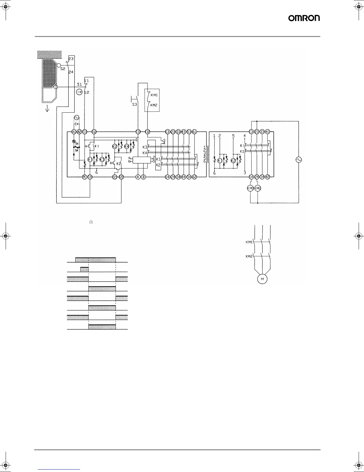
G9SA-501 (24 VAC/VDC) and G9SA-EX301 with 2-channel Limit Switch Input/Manual-reset
Feedback loop
Timing Chart
Open
Note: This circuit achieves EN954-1 Safety Category 4.
Control
circuit
S1: Safety Limit Switch
with direct opening mechanism
(D4N or D4B)
S2: Limit switch
S3: Reset switch
KM1 and KM2: Magnetic Contactor
M: 3-phase motor
Limit switches S1
and S2
Reset switch
S3
G9SA-501
K1, K2, K3 and
K4 (NC)
G9SA-501
K1, K2, K3, and
K4 (NO)
G9SA-EX301
K1 and K2 (NC)
G9SA-EX301
K1 and K2 (NO)
KM1 and KM2
(NC)
KM1 and KM2
(NO)
F502-EN2-04.book Seite 118 Dienstag, 26. Juli 2005 5:48 17

Other manuals for Omron G9SA

Questions and Answers:

Question and Answer IconNeed help?

Do you have a question about the Omron G9SA and is the answer not in the manual?

Omron G9SA Specifications

General IconGeneral
Rated Current6A
Mounting TypeDIN Rail
Dimensions90mm x 22.5mm x 100mm
WeightApprox. 200g
Safety CategoryCategory 4
Rated Voltage24 VDC
Operating Temperature-10°C to 55°C
Contact Rating6A at 250V AC
Electrical Life100, 000 operations
Mechanical Life10, 000, 000 operations

Related product manuals