H5BR
H5BR
14
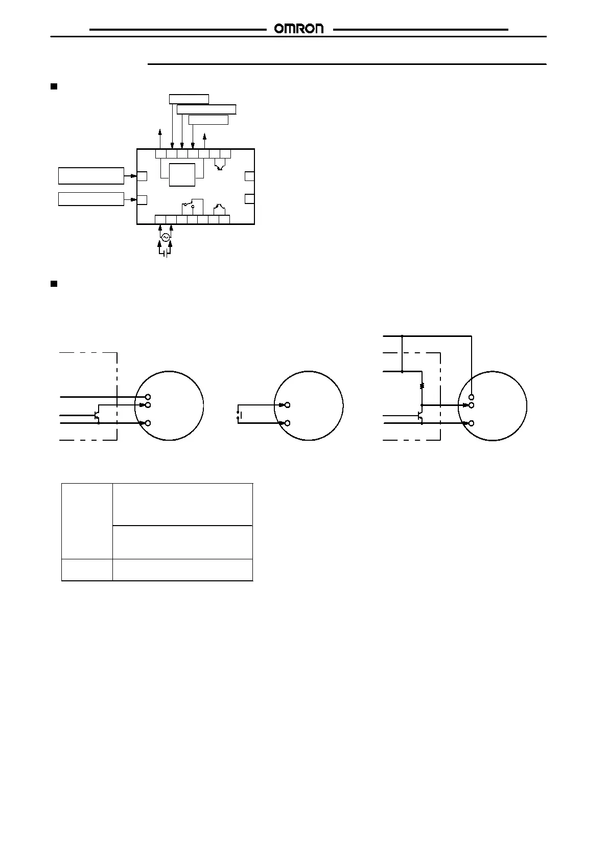
Installation
Te rminal Arrangement
6531
2
47
Gate input
12 V
Reset input
Start signal input
Batch count reset
input
Key protect input
OUT
100 to 240 VAC/24 VAC
12 to 24 VDC
15
16
17
18
H5BR-B (Standard)
Contact and
Transistor outputs
OUT
89
10 11 1312 14
Batch
External
power
supply
(-)
(+)
Common
0V
(-)
(+)
Unused
Unused
Note:
Do not connect unused terminals.
Connections
The inputs of the H5BR are no-voltage (short circuit or open) inputs.
No-voltage Input Signal Levels
No-contact
input
Contact
input
1. High level
Transistor ON
Residual voltage: 2 V max.
Impedence when ON: 1 k
"
max.
2. Low level
Transistor OFF
Impedence when OFF: 100 k
"
min.
Use contacts which can adequate-
ly switch 2 mA at 5 V
No-contact Input
(NPN Transistor)
Contact Input No-contact Input
Sensor
Timer
High: transistor ON
Timer
High: contact ON High: transistor ON
Sensor
Timer
12 VDC
Start signal,
reset, etc.
Input use 0 V
Start signal,
reset, etc.
Input use 0 V
12 VDC
+V (30 V max.)
Input use 0 V
Start signal,
reset, etc.

 Loading...


