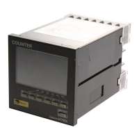
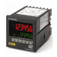
12 Cam Positioner H8PS
Dimensions
Note: All units are in millimeters unless otherwise indicated.
■ Main Unit
Cam Positioners
52.9
46
(14.6)
12
91.8 × 91.8
15.2
M3.5 terminal screw
96
96
21.6
52.9
46
(14.6)
12
91.8
× 91.
15.2
M3.5 terminal screw
96
96
21.6
14.6
Mounting panel
(1 to 5 mm)
α
52.9
52.3 + α
11 dia.
Mounting bracket (included)
Mounting screws
(2 included) (M4 x 12)
92
+0.8
0
92
+0.
0
Flush Mounting Models
H8PS-8B@ (8-output Models)
Panel Cutout
(according to DIN 43700)
Note: Mounting panel thickness must be 1 to
5 mm.
Flush mounting
Note: An 8-output Model is shown in the above
diagrams. The Encoder is connected
from the bottom with 16-/32-output
Models.
H8PS-16B@ (16-output Models)
H8PS-32B@ (32-output Models)
115.2±
0.3
Four, M4 ta
holes
81.8±
0.2
74.4
(See note 1.)
60.6
DIN Track
DIN Track Mounting Base
Y92F-91
(Order Separately)
16 16
(60.6)
58
46
22.9
16
91.8 × 91.8
M3.5 terminal screw
96
96
90
121.2
Terminal cover
M3.5 terminal screw
96
96
90
(60.6)
58
46
16
121.2
22.9
91.8 × 91.8
Terminal cover
Mounting holes
Surface
Mounting
Note: 1. These dimensions vary with the kind
of DIN track (reference value).
2. An 8-output Model is shown in the
above diagrams. The Encoder is
connected from the bottom with 16-/
32-output Models.
H8PS-16BF@ (16-output Models)
H8PS-32BF@ (32-output Models)
Track
Mounting
Surface Mounting Models
H8PS-8BF@ (8-output Models)