Multifunction Counter H7BX 5
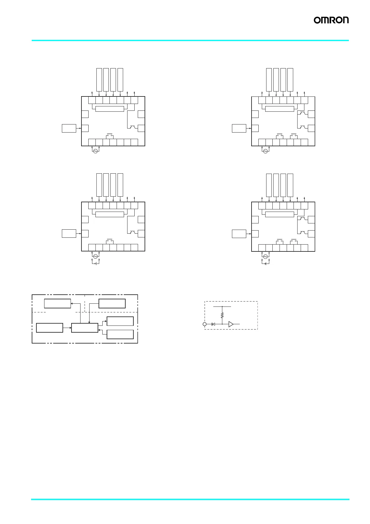
Connections
■ Terminal Arrangement
Confirm that the power supply meets specifications before using the H7BX.
H7BX-A H7BX-AW
H7BX-AD1 H7BX-AWD1
Note: Do not use the unused terminals for relay connections.
■ Block Diagram ■ Input Circuits
● CP1, CP2, Reset/Reset 1, and Total Reset/Reset 2 Input
Unused.
Unused.
Unused.
Unused.
0 V
Reset 1
CP2
CP1
Reset 2
12 VDC
Output COM
8 9 10 11 12 13 14
(−) (+)
External power supply
16
15
18
Unused.
17
Key
protection
OUT
OUT
1234567
0 V
8 9 10 11 12 13 14
16
15
18
17
OUT2
OUT1
OUT2 OUT1
1234567
Reset 1
CP2
CP1
Reset 2
12 VDC
Output COM
(−) (+)
External power supply
Key
protection
Unused.
Unused.
0 V
8 9 10 11 12 13 14
16
15
18
17
OUT
OUT
1234567
(−) (+)
Reset 1
CP2
CP1
Reset 2
12 VDC
Output COM
(−) (+)
Key
protection
External power supply
Unused.Unused.
Unused.
Unused.
Unused.
0 V
8 9 10 11 12 13 14
16
15
18
17
OUT2
OUT1
OUT2 OUT1
1234567
(−) (+)
Reset 1
CP2
CP1
Reset 2
12 VDC
Output COM
(−) (+)
Key
protection
External power supply
Unused.
Unused.
Output circuit
Internal control
circuit
Display circuit
Key switch
circuit
Input circuit
Power supply
circuit
(Basic insulation)
(Basic insulation)
Internal
circuit
IN
+14 V
1 kΩ
Note: The circuit shown above is for
no-voltage input (NPN input).