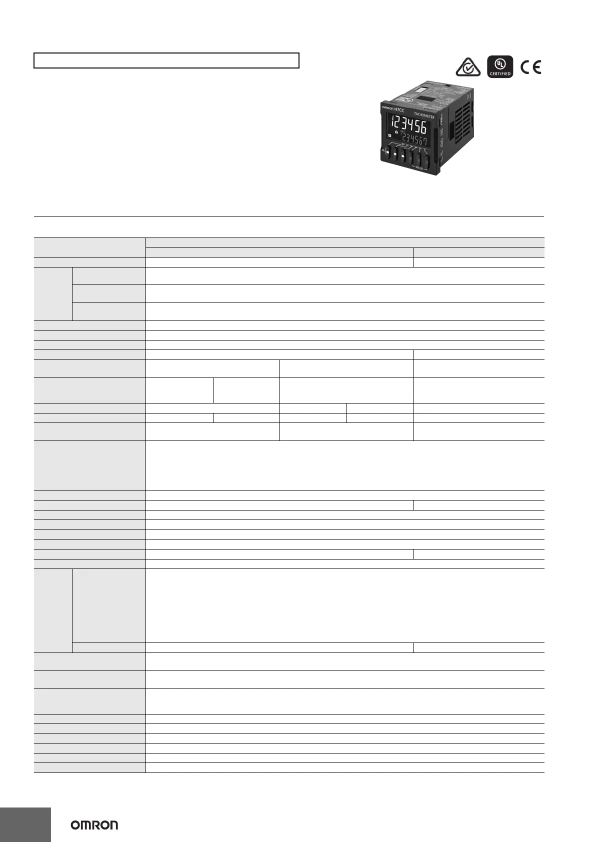
H7CC-R@
42
• Equipped with a replacement time notification function.
• The white-color display further improves visibility and the color
universal design is used. And the Up/Down Keys make it easier
to use the Tachometer.
• Compatible with the ratings, characteristics, and functionality of
the H7CX-R-N.
Specifications
Ratings
*1. Do not use the output from an inverter as the power supply. The ripple must be 20% maximum for CC power.
*2. The display is lit only when the power is ON. Nothing is displayed when power is OFF.
H7CC-R@ Tachometer
Classification Tachometer
Item Model H7CC-R11@ H7CC-R11W@
Input mode 1 input only 2 inputs only
Ratings
Power supply volt-
age *1
• 100 to 240 VAC, 50/60 Hz
• 12 to 24 VDC or 48 VAC, 50/60 Hz
Operating voltage
fluctuation range
85% to 110% of rated supply voltage (90% to 110% at 12 to 48 VDC)
Power consumption
Approx. 6.8 VA at 100 to 240 VAC,
Approx. 5.5 VA/ 3.3 W at 24 VAC/12 to 48 VDC
Mounting method Flush mounting or surface mounting
External connections 11-pin socket
Degree of protection IEC IP66 for panel surface only and when Y92S-29 Waterproof Packing is used
Input signals Count and hold Count 1 and count 2
Pulse measurement method Tachometer mode (cycle measurement)
AMD-compatible mode (continuous
measurement)
Tachometer mode (cycle measurement)
Maximum counting speed
30 Hz
(minimum pulse
width: 16.7 ms)
10 kHz
(minimum pulse
width: 0.05 ms)
---
30 Hz (minimum pulse width: 16.7 ms) or
5 kHz (minimum pulse width: 0.1 ms)
(selectable)
Minimum input signal width --- 10 ms 1 ms ---
Measuring ranges
0.001 Hz to 30.00Hz
0.001 Hz to 10 kHz
0.026 to 999999 s 0.003 to 999999 s 0.01 to 5k Hz
Sampling cycle 200 ms min.
Continuous measurement (minimum
interval of 10 ms)
200 ms min.
Display refresh cycle
• Input pulse of 5 Hz min.
Averaging not used: 200 ms
Averaging used: 200 multiplied by the averaging setting (ms)
• Input pulse of less than 5 Hz
Averaging not used: Two times the maximum input pulse cycle
Using averaging: Two times the maximum of the input pulse cycle multiplied by the averaging setting.
Measuring accuracy ±0.1% FS ±1 digit max. (at 23 ±5°C)
Output mode HI-LO, AREA, HI-HI, LO-LO HI-HI, LO-LO
Auto-zero time 0.1 to 999.9 s (in Tachometer Mode)
Startup time 0.0 to 99.9 s
Averaging Simple averaging/moving averaging selectable, Number of times: OFF, 2, 4, 8 or 16 times
Prescaling function 0.001 to 99.999 (in Tachometer Mode)
Decimal point adjustment Rightmost 3 digits ---
Sensor waiting time 290 ms max. (Control output is turned OFF and no input is accepted during sensor waiting time.)
Input
Input method
No-voltage Input
Impedance when ON: 1 kΩ max.
(Leakage current: 12 mA when 0 Ω)
ON residual voltage: 3 V max.
Impedance when OFF: 100 kΩ min.
Voltage Input
High (logic) level: 4.5 to 30 VDC
Low (logic) level: 0 to 2 VDC
(Input resistance: approx. 4.7 kΩ)
Hold input Minimum input signal width: 20 ms ---
External power supply
12 VDC (±10%), 100 mA
* Refer to Safety Precautions (Common) on page 61 for details.
Control output
Contact output: 3 A at 250 VAC/30 VDC, resistive load (cosφ=1)
Minimum applied load:10 mA at 5 VDC (failure level: P, reference value)
Display *2
7-segment, negative transmissive LCD
Character height
Present value: 10 mm (white), comparison value: 6 mm (green)
Digits 6 digits (0 to 999999)
Memory backup Non-volatile memory (overwrites: 100,000 times min.) that can store data for 10 years min.
Operating temperature range −10 to 55°C (−10 to 50°C if Counter/Tachometers are mounted side by side) (with no icing or condensation)
Storage temperature range −25 to 70°C (with no icing or condensation)
Operating humidity range 25% to 85%
Case color Black (N1.5)
For the most recent information on models that have been certified for
safety standards, refer to your OMRON website.

 Loading...