Do you have a question about the Omron H7CC-A Series and is the answer not in the manual?
The improved user interface is intuitive and offers better overall visibility.
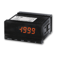
Details on the white-color display, Up/Down keys, status indicators, and reduced body depth.
Covers replacement time notification and isolated power supply/input circuits.
Highlights compatibility, output allocation, and memory backup functions.
Prevents abnormalities due to malfunctioning or setting errors.
Confirms compatibility with H7CX-N ratings and functionality.
Allows changing the allocation of outputs 1 and 2 (OUT1 and OUT2).
Enables turning the output OFF when the set value is reached.
Supports setting of the present value and output state memory backup.
Enables setting to start counting from 999999 when the present value exceeds 0.
Explains the structure of model numbers for H7CC series.
Details the configurations available for H7CC-A and H7CC-R series models.
Provides a legend for understanding model number symbols.
Lists available models with their specifications and part numbers.
Details the H7CC-A and H7CC-R series models and their configurations.
Lists optional accessories like covers, adapters, and sockets.
Protective soft cover accessory (Model: Y92A-48F1).
Protective hard cover accessory (Model: Y92A-48).
Adapter for flush mounting the unit.
Packing for achieving IP66 protection level.
Details front and back connecting sockets for the H7CC.
Terminal covers to create a finger-safe construction.
Optional products for mounting on DIN tracks.
Comprehensive technical specifications for the H7CC-A.
Details power supply, voltage fluctuation, and power consumption.
Specifies flush or surface mounting options.
Information on 8-pin/11-pin socket and screw terminals.
Details on input signal types and maximum counting speed.
Specific parameters for counter operation like input mode and output mode.
Describes the 7-segment LCD display and digit size.
Details the non-volatile memory capabilities.
Specifies the ambient operating temperature range.
Lists included accessories like flush mounting adapter.
Specifications specific to the tachometer function.
Details electrical and environmental characteristics.
Specifies insulation resistance values.
Details dielectric strength test values.
Specifies impulse withstand voltage ratings.
Details static immunity test levels.
Specifies vibration resistance test levels.
Details shock resistance test levels.
Provides mechanical and electrical life expectancy.
Specifies the weight of the unit.
Graphical representation of life expectancy based on load current.
Lists cULus, EN, EMC, and other relevant safety standards.
Details safety standards like cULus, EN, and EAC.
Specifies EMC standards including immunity and emission.
Explains the input/output functions of the H7CC-A.
Details how to use the H7CC-A as a counter.
Describes CP1, CP2, and Reset/Reset 1 inputs.
Explains Total Reset/Reset 2 and OUT1, OUT2 outputs.
Shows the delay time from reset signal to output OFF.
Guide for operating the tachometer function.
Provides terminal arrangement diagrams for various models.
Illustrates terminal layouts for different H7CC-A models.
Explains transistor output characteristics and connection.
Shows the internal block diagram of the H7CC-A.
Details CP1, CP2, Reset/Reset 1, and Total Reset/Reset 2 inputs.
Illustrates various input connection methods (NPN, PNP).
Describes connections for NPN inputs (Open Collector, Voltage Output, etc.).
Describes connections for PNP inputs (No-contact, Contact).
Specifies signal levels for no-contact and contact inputs.
Specifies signal levels for voltage inputs.
Details requirements for two-wire sensors.
Identifies and explains the parts of the H7CC-A unit.
Explains the indicators and displays on the unit.
Details the function of each key (Up, Down, Mode, Reset).
Describes the key-protect switch.
Explains the function and settings of the key-protect switch.
Provides overall dimensions for various H7CC-A models.
Dimensions for counter models without flush mounting adapter.
Physical dimensions for flush mounting without adapter.
Dimensions when using the flush mounting adapter.
Specifies required panel cutout dimensions for installation.
Physical dimensions when using a front connecting socket.
Lists optional accessories and notes on their condition.
Protective soft cover accessory (Model: Y92A-48F1).
Protective hard cover accessory (Model: Y92A-48).
Adapter for flush mounting the unit.
Guidance on protecting the unit from oil exposure.
Details on waterproof packing for IP66 protection.
Details dimensions, terminal arrangement, and mounting for sockets.
Dimensions and terminal layout for front sockets (P2CF-11, P2CF-11-E).
Dimensions and terminal layout for back sockets (P3GA-11, P3GA-08).
Terminal covers for creating finger-safe construction.
Lists optional mounting tracks and related accessories.
General guidelines for operating the counter.
Step-by-step guide for setting up counter operations.
Specific settings for counter mode operations.
Details on input/output functions for counter usage.
Explains how to enter and use the function setting mode.
Setting the prescale value for converting input pulses.
Setting the input mode to NPN or PNP.
Setting absolute value or forecast value for set value 1.
Setting the upper limit for the set value.
Setting the upper limit for the forecast set value.
Setting the upper limit for the batch count value.
Setting the key protect level to prevent unauthorized operation.
Details settings for output allocation, inversion, and memory backup.
Specifies output allocation for H7CC-W(U) models.
Sets logical inversion for output ON/OFF.
Enables or disables memory backup for present value and output state.
Enables H7AN compatibility for counting and replacement.
Sets the alarm value for the output ON count.
Monitors the output ON count for outputs 1 and 2.
Detailed explanation of various functions.
Explains input/output functions for counter operation.
Sets the input mode (increment, decrement, etc.).
Sets calculation mode (ADD or SUB) for dual counters.
Sets how control output is generated based on present value.
Sets the duration for one-shot output.
Sets the maximum counting speed for CP1 and CP2 inputs.
Sets the signal width for reset inputs.
Sets the decimal point position for display values.
Sets the prescale value to convert input pulses to desired units.
Selects NPN or PNP input format.
Sets absolute value or forecast value for set value 1.
Monitors the output ON count value (displayed only).
Monitors output ON count values for OUT1 and OUT2.
Specifies output allocation for H7CC-W(U) models.
Sets logical inversion for output ON/OFF.
Enables or disables memory backup for present value and output state.
Enables H7AN compatibility for counting and replacement.
Configures status indicator to display present value ratio.
Sets cumulative run time for replacement time notification.
Displays the cumulative run time.
Explains how to set values and operate in run mode.
Details I/O functions for various counter operations.
Operation details for the 1-stage preset counter mode.
Operation details for the total and preset counter mode.
Operation details for the dual counter mode.
Operation for 2-stage counter with absolute value setting.
Operation details for the batch counter mode.
Operation for 2-stage counter with forecast value setting.
Operation details for the twin counter mode.
Explains input modes and present value behavior.
Details input/output functions for counter operation.
Illustrates UP mode operation with CP1/CP2 inputs.
Illustrates DOWN mode operation with CP1/CP2 inputs.
Operation diagram for UP/DOWN A command input.
Operation diagram for UP/DOWN B individual input.
Operation diagram for UP/DOWN C quadrature input.
Operation diagram for UP/DOWN D command input.
Operation diagram for UP/DOWN E individual input.
Operation diagram for UP/DOWN F quadrature input.
Details input/output mode settings and operation.
Explains I/O functions for counter operation.
Explains settings for output modes N and F.
Details operation for output mode N.
Details operation for output mode F.
Explains settings for output modes C and R.
Details operation for output mode C.
Details operation for output mode R.
Explains settings for output modes K-1 and P.
Details operation for output mode K-1.
Details operation for output mode P.
Explains settings for output modes Q and A.
Details operation for output mode Q.
Details operation for output mode A.
Explains settings for output modes K-2, D, L, and H.
Details operation for output mode K-2.
Details operation for output mode D.
Details operation for output mode L.
Details operation for output mode H.
Explains the operation of the total and preset counter.
Explains the operation of the batch counter.
Explains the operation of the dual counter.
Explains the operation of the twin counter.
Lists reset operations for different counter functions.
Details I/O functions for counter operation.
Guide for setting up tachometer operations.
Explains how to set and operate the tachometer function.
Explains how to enter and use the function setting mode.
Sets the output mode for tachometer comparison.
Sets the counting speed for tachometer inputs.
Sets the decimal point position for tachometer display.
Details tachometer settings: Prescale, Averaging, Auto-zero time.
Sets the prescale value for tachometer measurements.
Selects between simple or moving averaging.
Sets the number of times for average processing.
Sets the time for force-setting frequency to 0.
Sets a prohibited measurement period at startup.
Selects NPN or PNP input mode.
Enables or disables peak/bottom hold function.
Sets output hysteresis to prevent chattering.
Delays the timing for turning OFF comparative output.
Sets the upper limit for the set value.
Sets the allocation of outputs 1 and 2.
Sets the key protect level.
Details tachometer settings: Output inversion, indicator mode, alarms.
Sets logical inversion for output 1 and output 2.
Configures status indicator to display measurement value ratio.
Sets/monitors output ON count alarm.
Sets cumulative run time for replacement notification.
Displays the cumulative run time.
Displays the software version of the unit.
Detailed explanation of tachometer functions.
Explains basic functions of tachometer operation.
Explains tachometer and AMD-compatible modes.
Use to measure pulse frequency (Hz).
Use to measure pulse cycle (s).
Sets maximum counting speed (30 Hz/10 kHz) for input.
Sets output method based on comparison value (HI-LO, AREA, etc.).
Selects averaging method (simple or moving).
Sets number of times for average processing.
Selects NPN or PNP input format.
Details advanced functions like decimal point and prescale.
Sets decimal point position for measurement/comparison values.
Sets prescale value to display rotation rate or speed.
Prohibits measurement for a set time at startup.
Records peak and bottom values after counting starts.
Prevents output chattering near the set value.
Delays the timing for turning OFF comparative output.
Sets the upper limit for the set value in run mode.
Sets the key protect level to prevent setting errors.
Sets measurement mode to pulse cycle or pulse width.
Sets display unit to Hz or seconds for pulse cycle measurement.
Sets measurement interval for 10 kHz pulse cycle measurement.
Sets alarm values for output ON counts.
Monitors output ON count values for outputs 1 and 2.
Sets the allocation of outputs 1 and 2.
Sets logical inversion for output ON/OFF.
Configures status indicator to display measurement value ratio.
Sets cumulative run time for replacement notification.
Displays the cumulative run time.
Explains how to set values and operate in run mode.
Displays the currently measured value.
Sets and compares measurement values to outputs.
Displays peak and bottom values after counting starts.
Displays peak/bottom values 1 and 2 after counting starts.
Explains output modes and their operation.
Operation for HI-LO output mode.
Operation for AREA output mode.
Operation for HI-HI output mode.
Operation for LO-LO output mode.
Output operation for Output 1.
Output operation for Output 2.
Important precautions for upper/lower limit output modes.
Guide to switching operating modes via configuration selection.
Explains how the hold function sustains display and output.
Details key protect levels (KP-1 to KP-7) and their effects.
Function for notifying replacement time based on cumulative run time.
Sets the cumulative run time alarm value.
Lists self-diagnostic displays and error correction methods.
Comprehensive technical specifications for the H7CC-R.
Details power supply, voltage fluctuation, and power consumption.
Details on input signal types for tachometer operation.
Specifies input methods (No-voltage, Voltage) and hold input.
Details electrical and environmental characteristics.
Graphical representation of life expectancy based on load current.
Lists compliance with safety and EMC standards.
Explains the input/output functions for tachometer operation.
Details electrical and environmental characteristics.
Specifies insulation resistance values.
Details dielectric strength test values.
Specifies impulse withstand voltage ratings.
Details static immunity test levels.
Specifies vibration resistance test levels.
Details shock resistance test levels.
Provides mechanical and electrical life expectancy.
Specifies the weight of the unit.
Lists compliance with safety and EMC standards.
Explains the input/output functions for tachometer operation.
Provides terminal arrangement and block diagrams.
Illustrates terminal layouts for H7CC-R11 and H7CC-R11W.
Shows the internal block diagram of the H7CC-R.
Details count and hold inputs for tachometers.
Explains count and hold input functions.
Describes connections for NPN inputs.
Describes connections for PNP inputs.
Illustrates various input connection methods for H7CC-R.
Details NPN input connections and signal levels.
Specifies signal levels for no-contact and contact inputs.
Details PNP input connections and signal levels.
Specifies signal levels for voltage inputs.
Details requirements for two-wire sensors.
Identifies and explains the parts of the H7CC-R unit.
Explains the indicators and displays on the unit.
Details the function of each key (Up, Down, Hold, Mode).
Describes the key-protect switch.
Explains the function and settings of the key-protect switch.
Provides overall dimensions for tachometer models.
Dimensions for tachometers without flush mounting adapter.
Physical dimensions for tachometers without adapter.
Specifies required panel cutout dimensions for installation.
Dimensions when using the flush mounting adapter.
Physical dimensions when using a front connecting socket.
Lists optional accessories and notes on their condition.
Protective soft cover accessory (Model: Y92A-48F1).
Protective hard cover accessory (Model: Y92A-48).
Adapter for flush mounting the unit.
Guidance on protecting the unit from oil exposure.
Details on waterproof packing for IP66 protection.
Refers to connection sockets details on page 13.
Refers to optional track mounting products on page 14.
Parameters can be set via front panel keys.
Explains how to enter and use the function setting mode.
Sets the output mode for tachometer comparison.
Sets the counting speed for tachometer inputs.
Sets the decimal point position for tachometer display.
Details tachometer settings: Prescale, Averaging, Auto-zero time.
Sets the prescale value for tachometer measurements.
Selects between simple or moving averaging.
Sets the number of times for average processing.
Sets the time for force-setting frequency to 0.
Sets a prohibited measurement period at startup.
Selects NPN or PNP input mode.
Enables or disables peak/bottom hold function.
Sets output hysteresis to prevent chattering.
Delays the timing for turning OFF comparative output.
Sets the upper limit for the set value.
Sets the allocation of outputs 1 and 2.
Sets the key protect level.
Details tachometer settings: Output inversion, indicator mode, alarms.
Sets logical inversion for output 1 and output 2.
Configures status indicator to display measurement value ratio.
Sets/monitors output ON count alarm.
Sets cumulative run time for replacement notification.
Displays the cumulative run time.
Displays the software version of the unit.
Detailed explanation of tachometer functions.
Explains pulse measurement methods and counting speed.
Explains tachometer and AMD-compatible modes.
Use to measure pulse frequency (Hz).
Use to measure pulse cycle (s).
Sets maximum counting speed (30 Hz/10 kHz) for input.
Sets output method based on comparison value (HI-LO, AREA, etc.).
Selects averaging method (simple or moving).
Sets number of times for average processing.
Selects NPN or PNP input format.
Details advanced functions like decimal point and prescale.
Sets decimal point position for measurement/comparison values.
Sets prescale value to display rotation rate or speed.
Sets time for force-setting frequency to 0 if no pulse.
Prohibits measurement for a set time at startup.
Records peak and bottom values after counting starts.
Prevents output chattering near the set value.
Delays the timing for turning OFF comparative output.
Sets the upper limit for the set value in run mode.
Sets the key protect level to prevent setting errors.
Sets the alarm value for the output ON count.
Monitors output ON count values for outputs 1 and 2.
Sets the allocation of outputs 1 and 2.
Sets logical inversion for output ON/OFF.
Configures status indicator to display measurement value ratio.
Sets cumulative run time for replacement notification.
Displays the cumulative run time.
Explains how to set values and operate in run mode.
Displays the currently measured value.
Sets and compares measurement values to outputs.
Displays peak and bottom values after counting starts.
Displays peak/bottom values 1 and 2 after counting starts.
Details key protect levels (KP-1 to KP-7) and their effects.
Function for notifying replacement time based on cumulative run time.
Sets the cumulative run time alarm value.
Lists self-diagnostic displays and error correction methods.
Explains output modes and their operation for tachometers.
Operation for HI-LO output mode.
Operation for AREA output mode.
Operation for HI-HI output mode.
Operation for LO-LO output mode.
Output operation for Output 1.
Output operation for Output 2.
Important precautions for upper/lower limit output modes.
Explains how the hold function sustains display and output.
Precautions for replacing AMD-S with H7CC-R11.
Shows terminal arrangements for AMD-S and H7CC-R11.
Guide for setting H7CC-R11 to function like AMD-S.
Details key settings for AMD-S replacement.
Compares characteristics of AMD-S and H7CC-R11.
General safety precautions for all H7CC counters.
Explains hazard warning symbols and their meanings.
Provides guidance for safe product usage.
Offers advice to prevent failure or malfunction.
Explains the meaning of product safety symbols.
Covers mounting, storage, environment, and wiring precautions.
Details on power supply, startup time, and noise prevention.
Covers inrush current, power supply capacity, and waveform issues.
Information on complying with EMC standards and insulation.
| Model | H7CC-A Series |
|---|---|
| Type | Digital Counter |
| Digits | 6 digits |
| Input Type | Contact |
| Power Supply | 12-24 VDC |
| Output | Relay or Transistor (depending on model) |
| Communication | RS-485 |
| Operating Temperature | -10°C to 55°C |
| Storage Temperature | -25°C to 65°C |
| Humidity | 35 to 85% (with no condensation) |
| Mounting | Flush mounting |