H7CC-A@
8
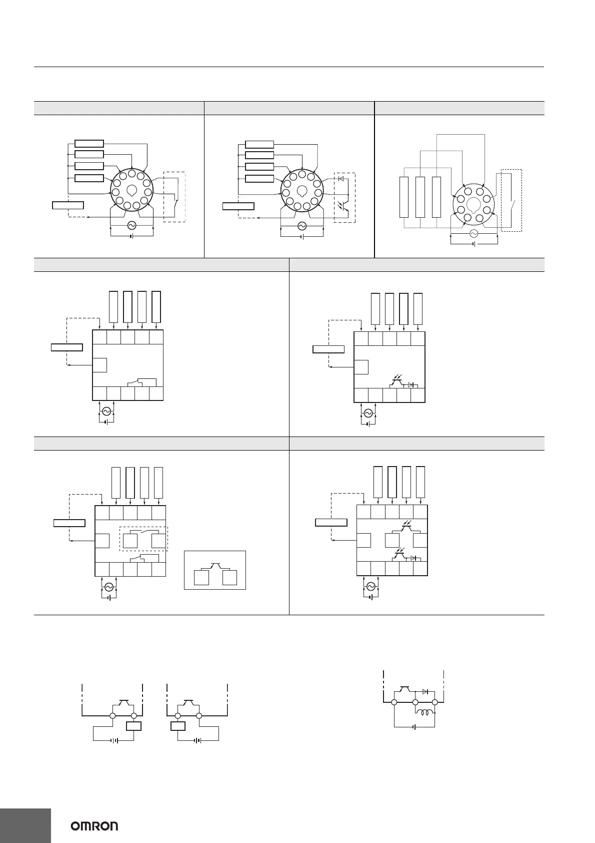
Connections
Terminal Arrangement
Confirm that the power supply meets specifications before use.
Transistor Output
• The transistor output of the H7CC is isolated from the internal
circuitry by a photocoupler, so the transistor output can be used as
both NPN and PNP output.
• The diode connected to the collector of the output transistor is used
to absorb inverted voltage that is generated when an inductive load
is connected to the H7CC.
H7CC-A11/-A11D H7CC-A11S/-A11SD H7CC-A8/-A8D
1-stage Contact Output 1-stage Transistor Output
1-stage Contact Output
H7CC-A/H7CC-AD H7CC-AS/-ASD
1-stage Contact Output
1-stage Transistor Output
H7CC-AW/-AWD/-AU/-AUD H7CC-AWS/-AWSD
2-stage Contact Output
2-stage Transistor Output
6
7
8
9
10
11
1
2
3
4
5
Reset
CP1
CP2
OUT
Total Reset
0 V
Internal
circuit
12 DCV
External
power supply
(-)
(-)
(+)
(+)
Sensor
6
7
8
9
10
11
1
2
3
4
5
OUT
Reset
CP1
CP2
Total Reset
0 V
Internal
circuit
12 DCV
(-)
(-)
(+)
(+)
Sensor
External
power supply
1
8
7
6
5
4
3
2
OUT
0 V
Internal
circuit
(-) (+)
Reset input
CP2 input
CP1 input
OUT
0 V
Reset
Total reset
CP2
CP1
12 VDC
External
power supply
(-)
(-)
(+)
(+)
Sensor
678910
11
12345
OUT
0 V
Reset
Total reset
CP2
CP1
12 VDC
External
power supply
(-)
(-)
(+)
(+)
Sensor
678910
11
12345
12 13
OUT1
OUT2
12 13
*1: H7CC-AU
*2
: OUT1 and OUT2 are
switchable by allocation change
*1
*2
*2
678910
11
0 V
12345
Sensor
12 VDC
External
power supply
(-)
(-)
(+)
(+)
Reset 1
CP2
CP1
Reset 2
12 13
OUT1
OUT2
*2: OUT1 and OUT2 are
switchable by allocation change
*1
*2
*2
678910
11
0 V
12345
Sensor
12 VDC
External
power supply
(-)
(-)
(+)
(+)
Reset 1
CP2
CP1
Reset 2
Power for load
+
Load
Power for load
+
Load
Power for load
+
Counter
Inductive
load

 Loading...