22
H7CC-A@
Counter
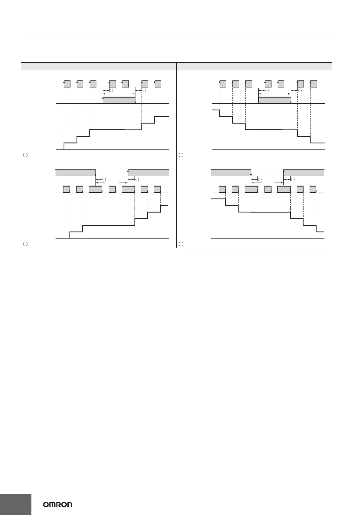
Input Modes and Present Value (See note 1.)
I/O Functions for Counter Operation
* Counting starts when the CP1 is turned ON after turning ON the power.
UP (Increment) Mode DOWN (Decrement) Mode
CP1: Count input; CP2: Prohibit (gate) input
must be greater than the minimum signal width. (See note 2.)
CP1: Count input; CP2: Prohibit (gate) input
must be greater than the minimum signal width. (See note 2.)
CP1: Prohibit (gate) input; CP2: Count input
must be greater than the minimum signal width. (See note 2.)
CP1: Prohibit (gate) input; CP2: Count input
must be greater than the minimum signal width. (See note 2.)
0
CP1
H
L
CP2
Present value
H
L
0
1
2
4
3
5
Prohibit
A A
n
CP1
H
L
CP2
Present value
H
L
0
n−1
n−2
n−4
n−3
n−5
A A
Prohibit
0
*CP1
H
L
CP2
Present value
H
L
0
1
2
4
3
5
A A
Prohibit
n
*CP1
H
L
CP2
Present value
H
L
0
n−1
n−2
n−4
n−3
n−5
A A
Prohibit

 Loading...