23
H7CC-A@
Counter
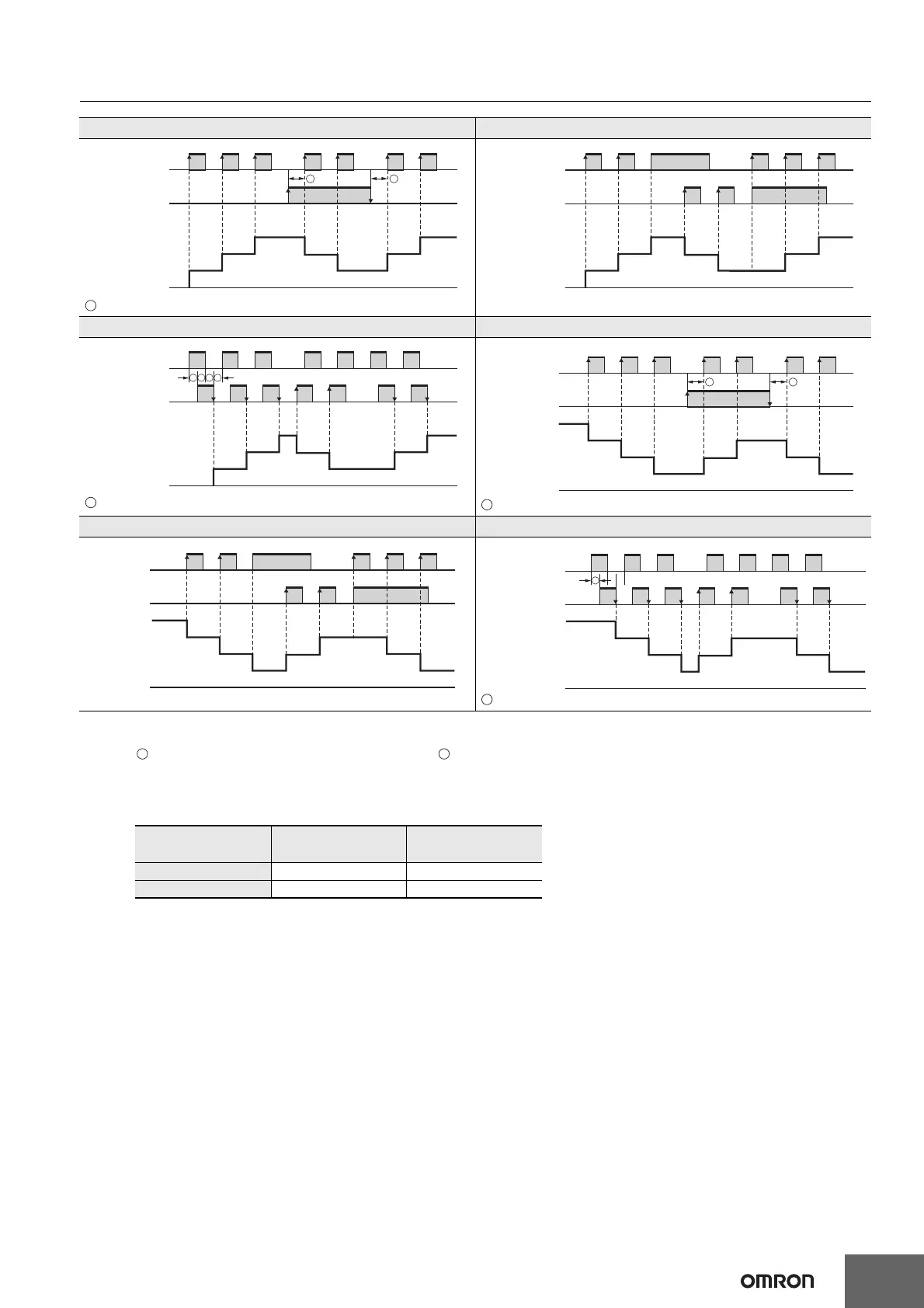
Note: 1. If the configuration selection is set to dual counter, CP1 and CP2 input will operate in the same way as the count input (CP1) of UP
(increment) mode.
2. must be greater than the minimum signal width and must be at least 1/2 the minimum signal width.
If they are less, a count error of ±1 may occur.
3. Minimum signal width: 16.7 ms (when maximum counting speed = 30 Hz)
100 µs (when maximum counting speed = 5 kHz)
4. The meaning of the H and L symbols in the tables is explained below.
UP/DOWN A Command Input Mode UP/DOWN B Individual Input Mode
must be greater than the minimum signal width. (See note 2.)
UP/DOWN C Quadrature Input Mode UP/DOWN D Command Input Mode
must be at least 1/2 the minimum signal width. (See note 2.)
must be at least 1/2 the minimum signal width. (See note 2.)
UP/DOWN E Individual Input Mode UP/DOWN F Quadrature Input Mode
must be at least 1/2 the minimum signal width. (See note 2.)
0
CP1
H
L
CP2
Present value
H
L
0
1
2
2
2
1
3
3
A A
0
CP1
H
L
CP2
Present value
H
L
0
1
2
2
2
11
3
3
0
CP1
H
L
CP2
Present value
H
L
0
1
2
2
2
1
3
3
B B B B
n
CP1
ON
OFF
CP2
ON
OFF
n-1
n-2
n-2
n-2
n-1
n-3
n-3
C
C
Present value
C
n
n-1
n-2
n-2
n-2
n-1 n-1
n-3
n-3
CP1
ON
OFF
CP2
Present value
ON
OFF
n-1
n
n-2
n-2
n-2
n-1
n-3
n-3
D
CP1
ON
OFF
CP2
ON
OFF
Present value
D
Input method
Symbol
No-voltage input
(NPN input)
Voltage input
(PNP input)
H Short-circuit 4.5 to 30 VDC
L Open 0 to 2 VDC

 Loading...