H7CR
H7CR
8
Timing Charts
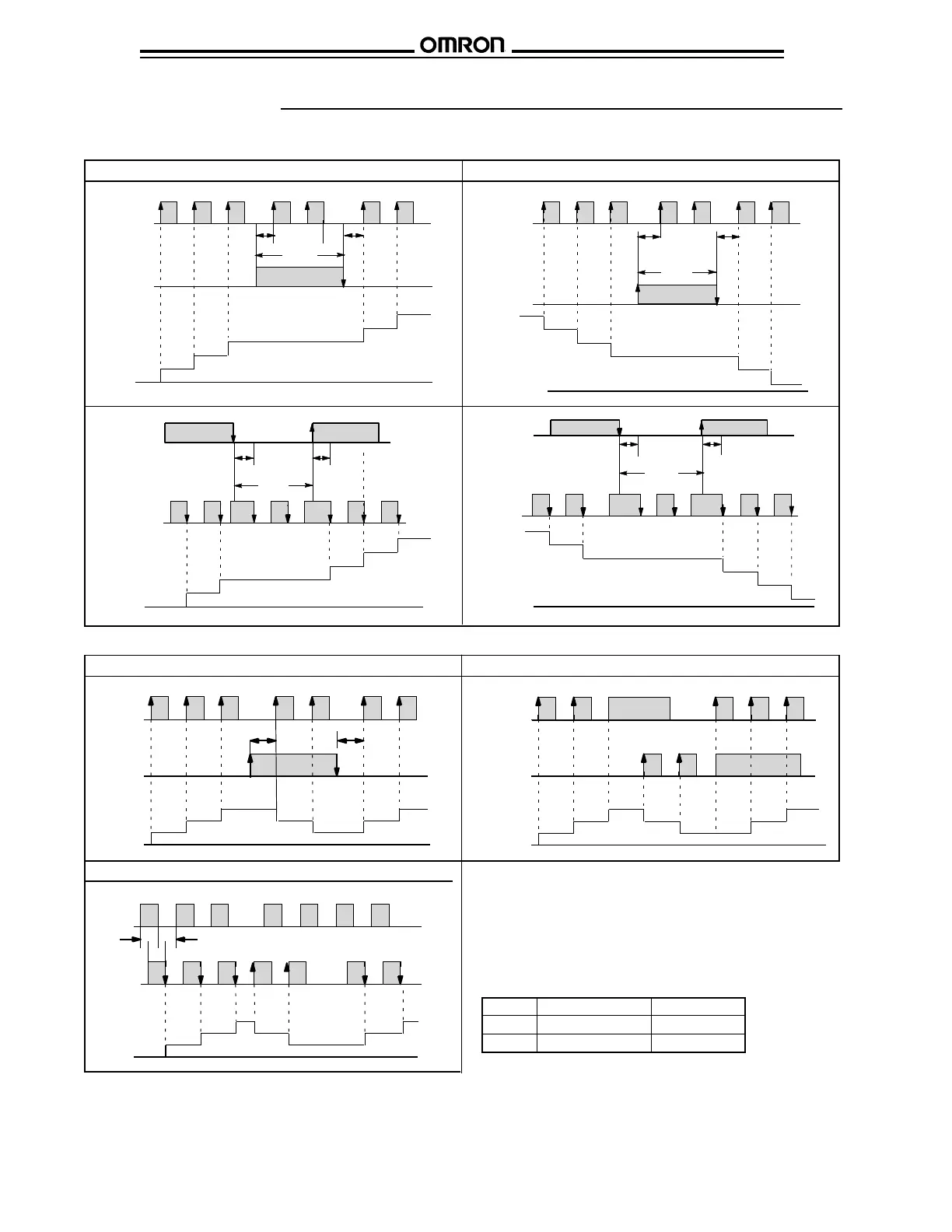
■ INPUT MODES
Count
H
L
H
L
0
1
2
3
4
Count
input
CP1
Gate
input
CP2
5
Inhibit
A A
0
Count
input
CP1
Gate
input
CP2
Count
H
L
H
L
n
n-1
n-2
n-3
n-4
0
Inhibit
A A
n-5
Gate
input
CP1
Count
input
CP2
Count
H
L
H
L
1
2
3
4
5
0
Inhibit
A A
0
Gate
input
CP1
Count
input
CP2
Count
H
L
H
L
0
n
n-1
n-2
n-3
n-4
n-5
Inhibit
A A
Up (increment) mode Down (decrement) mode
Up/Down A Command input mode Up/Down B individual input mode
H
L
CP2
Count
H
L
CP1
0
1
2
3
2
1
2
3
A
A
H
L
CP2
Count
H
L
CP1
0
1
2
3
2
11
2
3
2
H
L
H
L
0
1
2
3
1
2
3
BB BB
Count
Up/Down A Command input mode
Note 1 A: Minimum signal width.
B: Must be at least 1/2 of minimum signal width.
Signals may not be counted if the minimums for
A and B are not met.
Note 2 Set the same counting speed for CP1 and CP2 when
in Up/Down C mode.
Note 3 H and L
Signal No-voltage input Voltage input
H Short circuit 4.5 to 30 VDC
L Open circuit 0 to 2 VDC
 Loading...


