10 Timer Interval Indicator K3HB-P
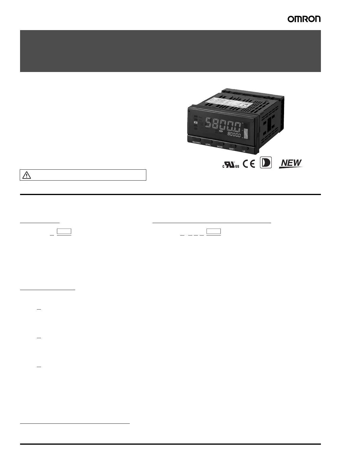
Timer Interval Indicator
K3HB-P
Digital Time Interval Meter for Measuring
Passing Speed, Time, or Cycle between Two
Points.
• Measures Wide Range of Pulse Interval Times
Measures, calculates, and displays pulse intervals between two
points. Wide range for pulse interval measurements, from 10 ms to
3,200 s, max.
• Six Measurement Operations, Including Passing Speed, Time,
and Cycle Measurement between Two Points
One Digital Time Interval Meter has six measurement functions, to
support a variety of pulse interval measurement applications. Select
the best function for your application from the following: Passing
speed, cycle, time difference, time band, measuring length, and
interval.
Refer to Common Precautions on page 30.
Model Number Structure
■ Model Number Legend
Base Units and Optional Boards can be ordered individually or as sets.
Note: 1. CPA can be combined with relay outputs only.
2. Only one of the following can be used by each Digital Indicator:
RS-232C/RS-485 communications, a linear output, or DeviceNet communications.
Accessories (Sold Separately)
K32-DICN: Special Cable (for event inputs with 8-pin connector)
K32-BCD: Special BCD Output Cable
Base Units
1. Input Sensor Codes
NB: NPN input/voltage pulse input
PB: PNP input
5. Supply Voltage
100-240 VAC: 100 to 240 VAC
24 VAC/VDC: 24 VAC/VDC
Optional Board
Sensor Power Supply/Output Boards
Relay/Transistor Output Boards
Event Input Boards
Base Units with Optional Boards
2. Sensor Power Supply/Output Type Codes
None: None
CPA: Relay output (PASS: SPDT) + Sensor power supply
(12 VDC±10%, 80 mA) (See note 1.)
L1A: Linear current output (DC0(4)-20 mA) + Sensor power supply
(12 VDC±10%, 80 mA) (See note 2.)
L2A: Linear voltage output (DC0(1)-5 V, 0 to 10 V) + Sensor power supply
(12 VDC±10%, 80 mA) (See note 2.)
A: Sensor power supply (12 VDC ±10%, 80 mA)
FLK1A: Communications (RS-232C) + Sensor power supply
(12 VDC±10%, 80 mA) (See note 2.)
FLK3A: Communications (RS-485) + Sensor power supply
(12 VDC±10%, 80 mA) (See note 2.)
3. Relay/Transistor Output Type Codes
None: None
C1: Relay contact (H/L: SPDT each)
C2: Relay contact (HH/H/LL/L: SPST-NO each)
T1: Transistor (NPN open collector: HH/H/PASS/L/LL)
T2: Transistor (PNP open collector: HH/H/PASS/L/LL)
BCD: BCD output + transistor output (NPN open collector: HH/H/PASS/L/LL)
DRT: DeviceNet (See note 2.)
4. Event input Type Codes
None: None
1: 5 points (M3 terminal blocks) NPN open collector
2: 8 points (10-pin MIL connector) NPN open collector
3: 5 points (M3 terminal blocks) PNP open collector
4: 8 points (10-pin MIL connector) PNP open collector
15
K3HB-P @
2
K33-@
3
K34-@
4
K35-@
1 2 3 4 5
K3HB-P@-@@@

 Loading...