22 Digital Indicators K3HB-R/-P/-C
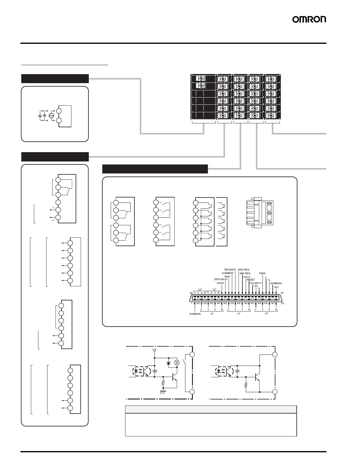
Connections
The BCD COMMON is shared.
The pins indicated in the above diagram
as blank (white) boxes have been removed.
*
Only one of the following can be used for each Digital Indicator: communications, BCD, or DeviceNet.
DeviceNet Connector (Included)
<DRT>
1 2 3 4 5
Relay Outputs
<C2>
Relay Outputs
<C1>
Transistor Outputs
<T1> <T2>
NPN
PNP
HH
H
PA SS
L
LL
COM
C1
C2
C3
C4
C5
C6
RS-232C
<FLK1A>
RS-485
<FLK3A>
B1
B2
B3
B4
B5
B6
B1
B2
B3
B4
B5
B6
B1
B2
B3
B4
B5
B6
<L2A> <L1A>
+
−
+
−
SD
RD
SG
N/C
12 VDC
80 mA
B (+)
A (−)
B (+)
A (−)
12 VDC
80 mA
12 VDC
80 mA
12 VDC
80 mA
0-20/
4-20 mA
N/C
0-5/1-5/
0-10 V
N/C
<A>
12 VDC
80 mA
+
−
+
−
+
−
<CPA>
12 VDC
80 mA
N/C
N/C
PA SS
Sensor
power
supply
B1
B2
B3
B4
B5
B6
HH
H
COM
L
H
L
LL
COM
C1
C2
C3
C4
C5
C6
C1
C2
C3
C4
C5
C6
Sensor
power
supply
Sensor
power
supply
Sensor power supply + communications
Sensor power supply
Sensor
power
supply
ABCDE
1
2
3
4
5
6
100 to 240 VAC
24 VAC/VDC
A1
A2
HH
H
L
LL
PASS
BCD (NPN Open Collector): <BCD>
Applicable Connector (Sold separately)
HDR-E50MAG1
(HONDA TSUSHIN KOGYO CO., LTD.)
Special Cable (Sold separately)
K32-BCD (OMRON)
(HDR-E50MAG1 with 0.3-m cable)
5 V
HH
H
L
LL
PASS
A Operating Power Supply
*Check the required power supply type.
Sensor power supply + PASS output
Sensor power supply + linear output
B Sensor Power Supply/Output
C
Relays, Transistors, BCD and DeviceNet
1: V− (Power supply cable: Black)
2: CAN L (Communications cable: Blue)
3: Shield
4: CAN H (Communications cable: White)
5: V+ (Power supply cable: Red)
Applicable Connector:
HR31-5.08P-5SC (01)
(HIROSE ELECTRIC CO., LTD.)
* Attach the provided crimp terminals.
Contact Outputs Transistor Outputs
(NPN Open Collector)
• Always use a EN/IEC-compliant power supply with reinforced insulation or double
insulation for the DeviceNet power supply.
• The product must be used indoors for the above applicable standards to apply.
Safety Standards Conformance
■
xterna
onnect
on
agrams
Terminal Arrangements
Note: Refer to “Internal Block Diagram” on page 24 for information on isolation.

 Loading...