Appendices
A - 60
NX-series Position Interface Units User’s Manual (W524)
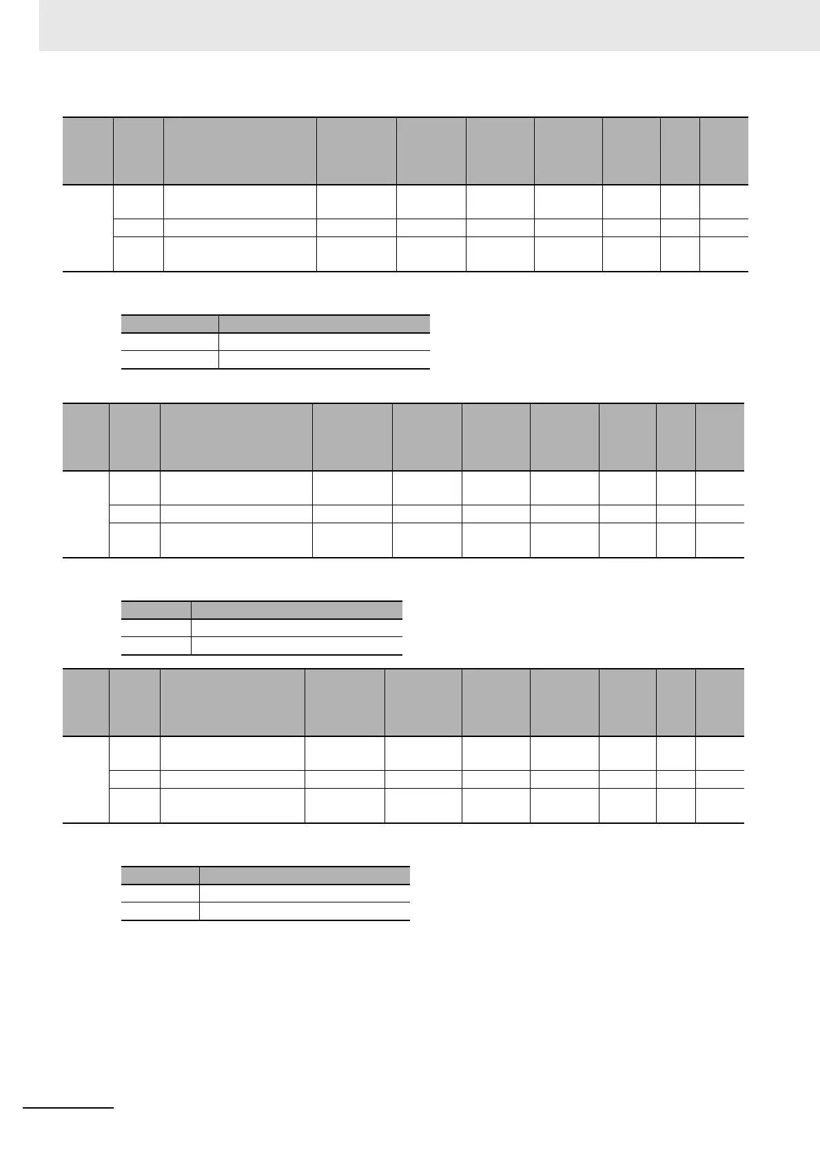
• The following table shows the settings for the External Input 0 Function Selection object.
• To use the latch, you must set the Latch Input 2 Trigger Selection bit to 0 (external input).
• The following table shows the settings for the External Input 1 Logic Selection object.
• The following table shows the settings for the External Input 1 Function Selection object.
• To use the latch, you must set the Latch Input 2 Trigger Selection bit to 0 (external input).
Index
(hex)
Subin-
dex
(hex)
Object name Default
Data
range
Unit Data type Access
I/O
allo-
cat-
ion
Data
attri-
bute
5012 --- External Input 0 Function
Selection
--- --- --- --- --- --- ---
00 Number of Entries 1 1 --- USINT RO No ---
01 Ch1 External Input 0
Function Selection
1 0 or 1 --- USINT RW No Y
Set value Description
0 General input
1 Latch input 1
Index
(hex)
Subin-
dex
(hex)
Object name Default
Data
range
Unit Data type Access
I/O
allo-
cat-
ion
Data
attri-
bute
5013 --- External Input 0 Logic
Selection
--- --- --- --- --- --- ---
00 Number of Entries 1 1 --- USINT RO No ---
01 Ch1 External Input 0
Logic Selection
0 0 or 1 --- USINT RW No Y
Set value Description
0 N.O. (Normally open)
1 N.C. (Normally close)
Index
(hex)
Subin-
dex
(hex)
Object name Default Data range Unit Data type Access
I/O
allo-
cat-
ion
Data
attri-
bute
5014 --- External Input 1 Func-
tion Selection
--- --- --- --- --- --- ---
00 Number of Entries 1 1 --- USINT RO No ---
01 Ch1 External Input 1
Function Selection
1 0 or 1 --- USINT RW No Y
Set value Description
0 General input
1 Latch input 2
 Loading...


