NX-CSG/SL5/SI/SO
16
Terminal Blocks
Terminal Blocks come in three types depending on the number of terminals that can be used. There are 8-terminal, 12-terminal, and 16-terminal
Terminal Blocks.
Only the 8-terminal type terminal block is compatible with Communication Control Unit.
To prevent incorrect insertion, terminal blocks in any other types besides the 8-terminal type cannot be mounted.
Applicable Terminal Blocks for Each Model
Current capacity of power supply terminals and applicable terminal blocks for each model of Communication Control Unit are shown in the following
table.
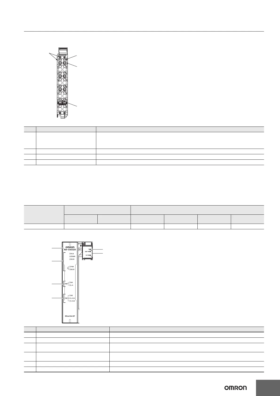
Indicators
Letter Name Function
(A) Terminal number indications
The terminal numbers are given by column letters A and B, and row numbers 1 to 8.
The combination of the "column" and "row" gives the terminal numbers from A1 to A8 and B1 to B8.
The terminal number indicators are the same regardless of the number of terminals on the terminal block, as shown
above.
(B) Release hole Insert a flat-blade screwdriver into these holes to connect or remove the wires.
(C) Terminal hole The wires are inserted into these holes.
(D) Ground terminal mark This mark indicates the ground terminals.
Unit model number
Current capacity of power supply
terminal for the Unit
Terminal block
Unit power supply I/O power supply
Terminal block
model
Number of
terminals
Ground terminal
mark
Terminal current
capacity
NX-CSG320 4 A NX-TBC082 8 Provided 10 A
Letter Name Function
(A) Model number display Displays the model information of Communication Control Unit.
(B) Communication Control Unit Status Indicators The indicators show the current operating status of Communication Control Unit.
(C)
Built-in EtherNet/IP Status Indicators
(PORT1)
The indicators show the communications status of Built-in EtherNet/IP Port (PORT1).
(D)
Built-in EtherNet/IP Status Indicators
(PORT2)
The indicators show the communications status of Built-in EtherNet/IP Port (PORT2).
(E) NX Bus Status Indicators These indicators show the communications status with Communication Control Unit and NX Units.
(F) Power Status Indicators Show the power supply status of the Unit and I/O power supply.
8-terminal type
(A)
A1
A2
A3
A4
A5
A6
A7
A8
B1
B2
B3
B4
B5
B6
B7
B8
(B)
(C)
NX-TBC082
(D)

 Loading...


