NX-CSG/SL5/SI/SO
17
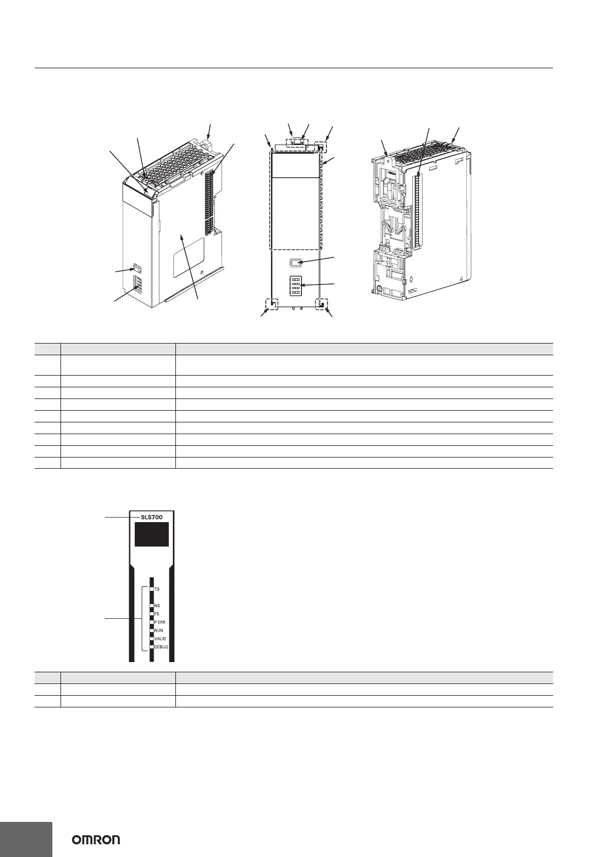
Safety Control Units
Safety CPU Units NX-SL5500/SL5700
Indicators
The Safety CPU Unit has indicators that show the current operating status and communications status.
Letter Name Function
(A) Marker attachment locations
The locations where markers are attached. The markers made by OMRON are installed for the factory setting.
Commercially available markers can also be installed.
(B) Protrusions for removing the Unit The protrusions to hold when removing the Unit.
(C) DIN Track mounting hook This hook is used to mount the NX Unit to a DIN Track.
(D) NX bus connector This is the NX-series bus connector.
(E) Unit hookup guides These guides are used to connect two Units.
(F) Indicators The indicators show the current operating status and power supply status of the Safety CPU Unit.
(G) Service switch This switch is used for the start trigger of various functions.
(H) DIP switch This switch is used for the Safety Unit Restore and the safety data logging function.
(I) Unit specifications The specifications of the Safety CPU Unit are given.
Letter Name Function
(A) Model number display Displays part of the model number of the Safety CPU Unit.
(B) Indicators Show the current operating status and communications status of the Safety CPU Unit.
(D)
(D)
(E)
(C)
(I)
(F)
(E)
(A)
(G)
(H)
(C)
(C)
(B)
(E)
(B)
(B)
(G)
(H)
(E)
(A)
(B)

 Loading...


