NX-CSG/SL5/SI/SO
9
Safety Input Units NX-SIH400/SID800
Unit name Safety Input Unit
Model NX-SIH400 NX-SID800
Number of safety input points 4 points 8 points
Number of test output points 2 points 2 points
Internal I/O common PNP (sinking inputs)
Rated input voltage 24 VDC (20.4 to 28.8 VDC)
OMRON special safety input
devices
Can be connected. Cannot be connected.
Number of safety slave
connections
1
I/O refreshing method Free-Run refreshing
External connection terminals Screwless clamping terminal block (8 terminals) Screwless clamping terminal block (16 terminals)
Indicators
TS indicator, FS indicator, input indicators (yellow), and input
error indicators (red)
TS indicator, FS indicator, input indicators (yellow), and input
error indicators (red)
Safety input current 4.5 mA TYP. 3.0 mA TYP.
Safety input ON voltage 11 VDC min. 15 VDC min.
Safety input OFF voltage/OFF
current
5 VDC max., 1 mA max.
Test output type Sourcing outputs (PNP)
Test output load current 25 mA max. 50 mA max.
Test output residual voltage 1.2 V max. (Between IOV and all output terminals)
Test output leakage current 0.1 mA max.
Dimensions 12 × 100 × 71 mm (W × H × D)
Isolation method Photocoupler isolation
Insulation resistance 20 M min. between isolated circuits (at 100 VDC)
Dielectric strength 510 VAC for 1 min between isolated circuits, leakage current: 5 mA max.
I/O power supply method Power supplied from the NX bus
Current capacity of I/O power
supply terminals
No applicable terminals.
NX Unit power consumption
• Connected to a CPU Unit or a Communication Control Unit
1.10 W max.
• Connected to a Communications Coupler Unit
0.70 W max.
• Connected to a CPU Unit or a Communication Control Unit
1.10 W max.
• Connected to a Communications Coupler Unit
0.75 W max.
Current consumption from I/O
power supply
20 mA max.
Weight 70 g max.
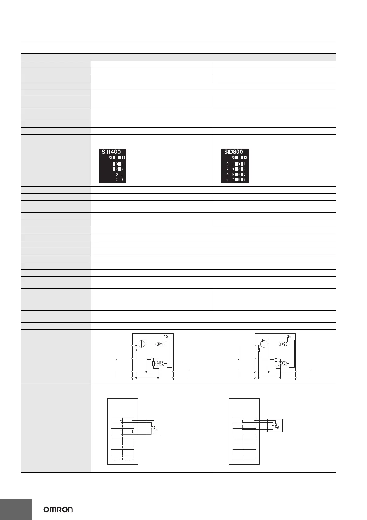
Circuit layout
Terminal connection diagram
Si0 to Si3: Safety input terminals
T0 and T1: Test output terminals
Refer to User's manual (Cat. No. P129-101) for details.
Si0 to Si7: Safety input terminals
T0 and T1: Test output terminals
Refer to User's manual (Cat. No. P129-101) for details.
Internal circuits
T0 and T1
Terminal block
Si0 to Si3
I/O power
supply +
I/O power
supply −
Left-side NX
bus connector
I/O power
supply +
I/O power
supply −
Right-side NX
bus connecto
Internal circuits
T0 and T1
Terminal block
Si0 to Si7
I/O power
supply +
I/O power
supply −
Left-side NX
bus connector
I/O power
supply +
I/O power
supply −
Right-side NX
bus connecto
Si0
NX-SIH400
Safety
Input Unit
A1 B1
A8 B8
Si1
T0 T1
Si2 Si3
T0 T1
Safety switch
Si0
A1 B1
A8 B8
Si1
T0 T1
Si2 Si3
T0 T1
Si4 Si5
T0 T1
Si6 Si7
T0 T1
NX-SIH800
Safety
Input Unit
Safety switch

 Loading...


