7.IO-Link Connection Procedure
38
18
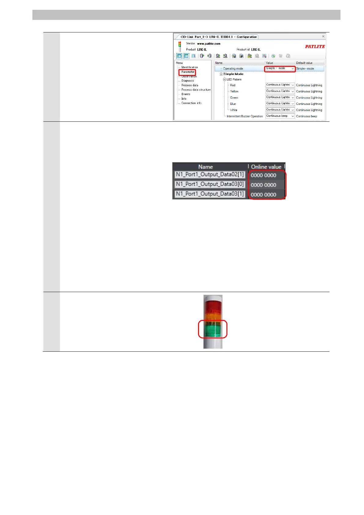
Select Parameter listed under Menu
on the <IO-Link Port_1:-> LR6-IL
IODD1.1 - Configuration Tab Page.
Check that Operating mode
displayed on the right side of the tab
page is set to Simple - mode
(default).
19
With Sysmac Studio, check that the
following online values are
displayed on the Watch Tab Page.
・N1_Port1_Output_Data02[1]:
0000 0000
・N1_Port1_Output_Data03[0]:
0000 0000
・N1_Port1_Output_Data03[1]:
0000 0000
*The bit 0 value of
N1_Port1_Output_Data02[1] is 0,
which indicates that Controller
turns OFF the green light of the
LED unit on Signal Tower.
*Refer to 6.4. Device Variables for
details on each of the variables.
Check that Signal Tower is not lit.
*As shown in the figure on the right,
Signal Tower is not lit. It is the
same as the online values
displayed in step 19.

 Loading...


