EasyManuals Logo

Omron NXR-ILM08C-EIT User Manual

Omron NXR-ILM08C-EIT
21 pages
To Next Page IconTo Next Page
To Previous Page IconTo Previous Page
Page #17 background imageLoading...
Page #17 background image
NXR-ILM08C-EIT
17
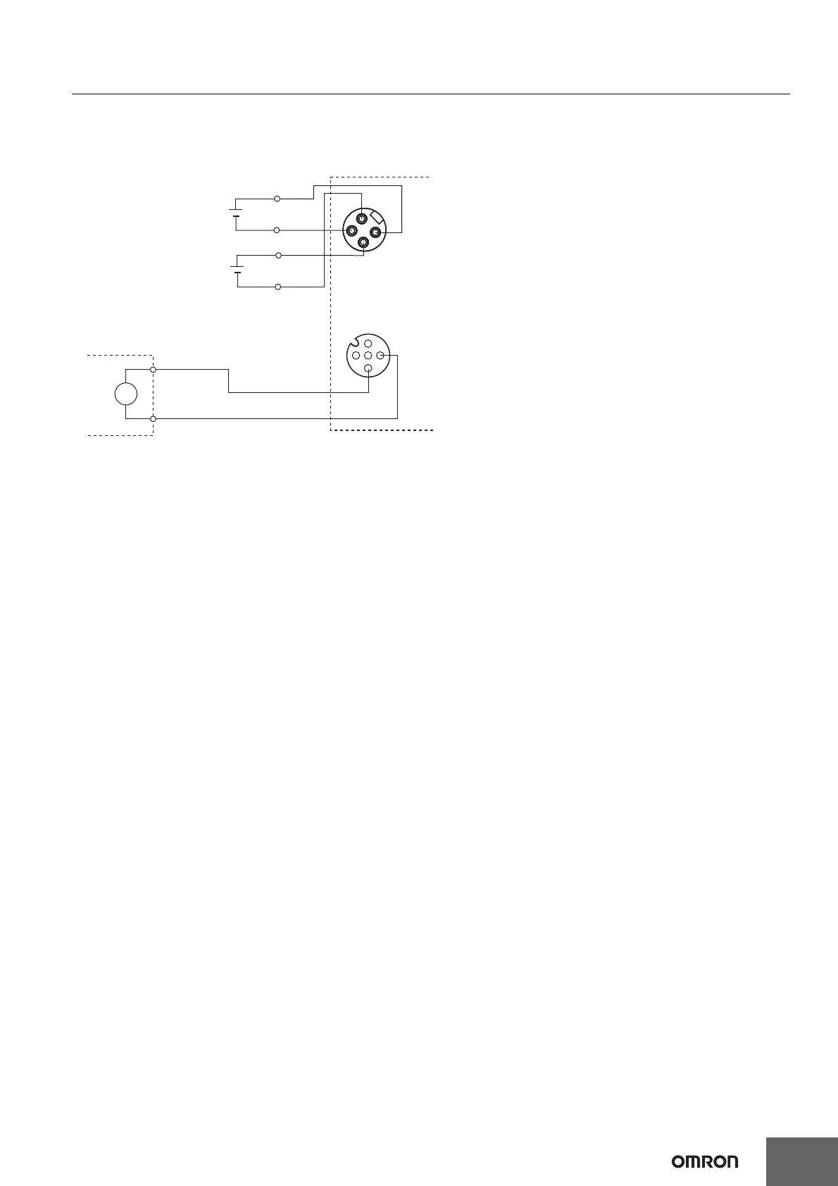
Wiring Example for Non-IO-Link Output Devices
A wiring example between the IO-Link Master Unit and a non-IO-Link output device is shown below.
In this example, the port is used in the following communications modes.
Pin 4: SIO (DO) Mode, pin 2: Disabled
4
2
3
1
2
1
3
4
U/IN P-
Non-IO-Link output device
U/IN P+
OUT P-
OUT P+
Output power supply
L
Power supply connector (input)
I/O connector
C/Q black
L- blue
IO-Link Master Unit
Unit/input power supply

Questions and Answers:

Question and Answer IconNeed help?

Do you have a question about the Omron NXR-ILM08C-EIT and is the answer not in the manual?

Omron NXR-ILM08C-EIT Specifications

General IconGeneral
BrandOmron
ModelNXR-ILM08C-EIT
CategoryTouch terminals
LanguageEnglish

Related product manuals