59
6. Using the UPS monitoring software and contact signal
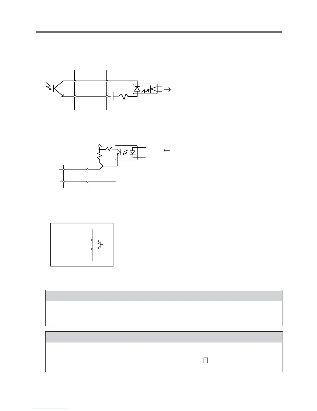
9. Example of the use of the Contact Signal circuit
● Example of the use of the BU signal
● Example of the use of the BS signal
● Example of remote ON/OFF
BU
COM
12V
1K Ω
System side
To port on PC
UPS side
TLP627
Connecting cable
(twisted or
shielded)
Remote ON/OFF
circuit
Notes
● When connecting a device that generates counter electromotive force to the signal output circuit
such as a relay, connect diodes to prevent counter electromotive force at the both end of the
relay.
Explanation
● When power is restored after the unit stopped automatically during a power failure, the unit
automatically restarts and supplies power. If you do not want to start the connected devices, turn
OFF their switches or set the auto restart setting (setting switch 2 ) to ON while the power is out.
(See page 33.)
10. Precautions and notes on the use of the Contact Signal
GND
BS
COM
System side
C2458
12V
1KΩ
1.2KΩ
TLP521
From port on PC
Connecting
cable (twisted
or shielded)
UPS side

 Loading...


