4 Configuration and Wiring
4 - 8
AC Servomotors/Servo Drives 1S-series with Built-in EtherCAT® Communications User’s Manual (I586)
• For the allowable axial loads for Servomotors, refer to
3-2-3 Characteristics on page 3-45. If an axial load
greater than that specified is applied to a Servomotor, it
may reduce the limit of the motor bearings and may
break the motor shaft.
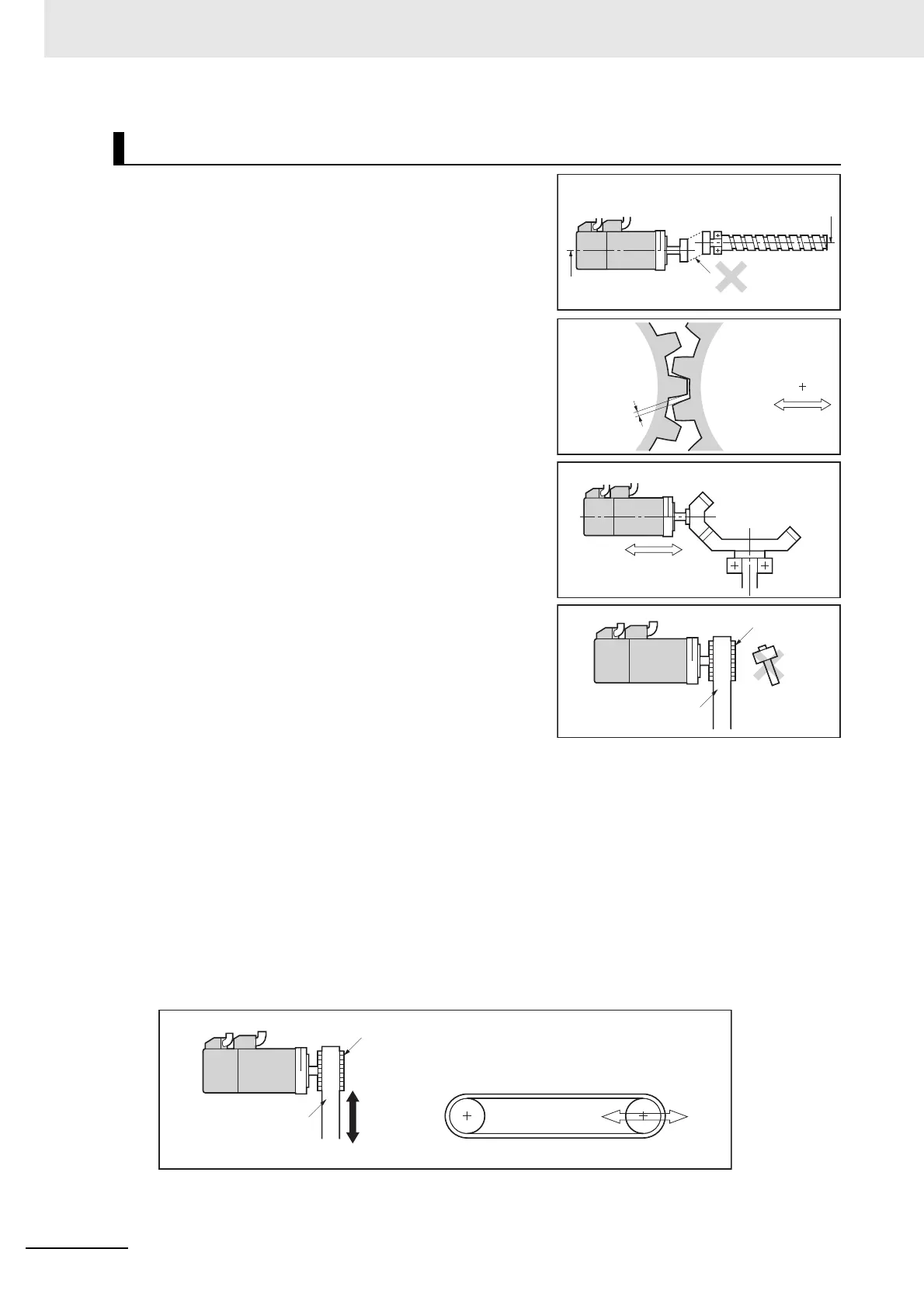
• When you connect the Servomotor to a load, use cou-
plings that can sufficiently absorb mechanical eccentric-
ity and declination.
• When you connect or disconnect loads (or couplings) to
or from the Servomotor, be careful not to apply an
impact on the motor shaft. Do not allow the thrust load
and radial load to exceed the values that are specified in
the manual or catalog while you connect a load to the
Servomotor.
• If an abnormal noise is generated from couplings, adjust
the shaft center again to eliminate the noise.
• When you align the shaft center of the couplings, turn
both the Servomotor side shaft and equipment side
shaft.
• For spur gears, an extremely large radial load may be
applied depending on the gear precision. Use spur
gears with a high degree of precision (for example, JIS
class 2: normal line pitch error of 6 µm max. for a pitch
circle diameter of 50 mm).
• If the gear precision is not adequate, allow backlash to
ensure that no radial load is placed on the motor shaft.
• When you use bevel gears, a load is applied in the
thrust direction depending on the assembly precision,
the gear precision, and temperature changes. Provide
appropriate backlash or take other measures to ensure that a thrust load larger than the specified
level is not applied.
• Do not put rubber packing on the flange surface. If the flange is mounted with rubber packing, the
Servomotor flange may crack under the tightening force.
• When you connect the Servomotor to a V-belt or timing belt, consult the manufacturer for belt selec-
tion and tension.
• A radial load twice as large as the belt tension will be placed on the motor shaft. Do not allow a load
that exceeds the allowable radial load to be placed on the motor shaft. If an excessive radial load is
applied, the motor shaft and bearings may be damaged.
Set up a movable pulley in the middle of the motor shaft and the load shaft so that the belt tension
can be adjusted.
Install the Servo Drive so that its bottom faces the gravity direction.
• The cable outlet direction of the Servomotor for power cable connector type M23 or M40 can be
selected. The below shows the selectable range. The change of the cable outlet direction shall be up
Connecting to Mechanical Systems
Pulley
Belt
Set a structure in which
the distance between
axes can be adjusted.
Backlash
Motor center line
Ball screw center line
Misalignment of
Misalignment of
shaft centershaft center
Misalignment of
shaft center
Set a movable
structure
Bevel gear
Pulley
Belt
Tension
Tension adjustment
(Set a movable structure.)
 Loading...

