8-42
8-5 Interface Monitor Setting Parameters
OMNUC G5-SERIES AC SERVOMOTOR AND SERVO DRIVE USER'S MANUAL
8
Parameter Details
Adjust the offset of the speed command input (REF: CN1 pin 18).
The offset amount is approx. the set value times 5 mV.
There are 2 ways to adjust the offset.
· Manual adjustment
· Automatic adjustment
The manual adjustment is as follows:
· To adjust the offset for individual drives, accurately input 0 V to the speed command input/
torque command input (REF/TREF1) (or connect to the signal ground), and then set this
parameter so that the motor does not rotate.
· If you use a position loop in the host device, set this parameter so that there are no
accumulated pulses at servo lock stop status.
The automatic adjustment is as follows:
This parameter will be automatically set when automatic offset adjustment is executed. Refer to
"Analog Input Automatic Offset Adjustment" (P.9-26) for the automatic offset adjustment method.
Set the first-order lag filter time constant in the speed command input (REF: CN1 pin 18).
Set the overflow level for speed command input (REF: CN1 pin 18) or torque command input
(TREF1: CN1 pin 14) using voltage after offset compensation.
Excessive analog input (Alarm No. 39) will be disabled if this parameter is set to 0.
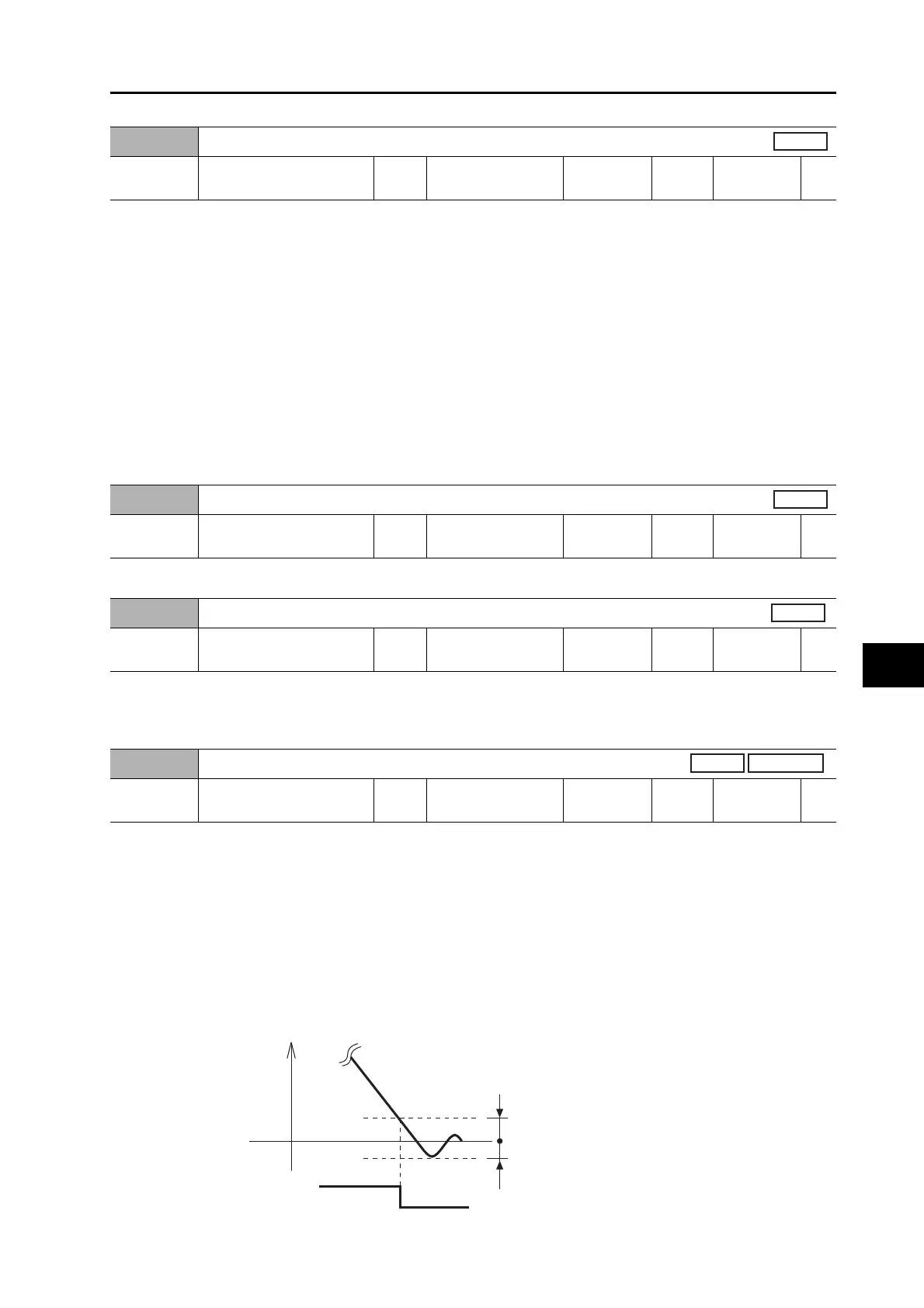
Use this parameter in combination with the Positioning Completion Condition Selection (Pn432) to set
the timing to output the positioning completion output (INP1). The positioning completion output (INP)
will output when the Servomotor (workpiece) movement stops and the number of the accumulated
pulses in the error counter is within the set value of this parameter, after command pulse input is
completed.
Unit for setting is command unit, but it can be changed to encoder unit with Position Setting Unit
Selection (Pn520). However, note that the unit for error counter overflow level will be changed as
well.
If this parameter is set to a very small value, the time required for the INP signal to be output will
increase and the chattering may occur during output. The setting of the positioning completion
range does not affect the precision of the final positioning.
Pn428
Analog Input 3 Offset
Setting
range
−342 to 342 Unit 5.86 mV
Default
setting
0
Power OFF
and ON
−
All
Pn429
Analog Input 3 Filter Time Constant
Setting
range
0 to 6,400 Unit 0.01 ms
Default
setting
0
Power OFF
and ON
−
Pn430
Excessive Analog Input 3
Setting
range
0 to 100 Unit 0.1 V
Default
setting
0
Power OFF
and ON
−
Pn431
Positioning Completion Range 1
Setting
range
0 to 262,144 Unit Command unit
Default
setting
10
Power OFF
and ON
−
Position
Fully-closed
INP
Accumulated
pulse
ON
Pn431
Pn431
 Loading...