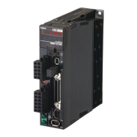
Do you have a question about the Omron R88D-KT30F and is the answer not in the manual?
| Model | R88D-KT30F |
|---|---|
| Type | Servo Drive |
| Manufacturer | Omron |
| Output Power | 3.0 kW |
| Applicable Motor Capacity | 3.0 kW |
| Communication | MECHATROLINK-II |
| Cooling Method | Natural Cooling |
| Protection Class | IP20 |
| Ambient Temperature | 0 to 55°C |
| Storage Temperature | -20 to 85°C |
| Input Voltage | 200-230 VAC |
| Series | R88D |
| Ambient Humidity | 90% RH or less (non-condensing) |
| Vibration Resistance | 4.9 m/s² {0.5G} |
Details precautions for safe use, including what to do and what not to do.
Details precautions for correct use to ensure proper operation and performance.
Measures include physical controls, network isolation, firewalls, VPNs, strong passwords, and virus scans for external storage.
Details general specifications, characteristics, connector specifications, and I/O circuits of the Servo Drives.
Details general specifications, characteristics, and encoder specifications of the Servomotors.
Explains position control performed based on pulse train input from the controller, using electronic gear for scaling.
Describes motor speed control based on analog voltage input from the controller, with options for position control integration.
Explains torque control based on analog torque command, requiring a speed limit input to prevent excessive motor speed.
Details motor speed control using up to 8 internally set speeds, selectable via control input terminals.
Explains using an external encoder for direct position detection and feedback for highly accurate positioning.
Explains how to use damping control to reduce vibration in mechanical units with low rigidity.
Explains the STO function used to cut off motor current and stop the motor via safety equipment connected to the safety connector (CN8).
Explains basic parameters like Rotation Direction Switching, Control Mode Selection, Realtime Autotuning Mode Selection, Inertia Ratio, and Command Pulse Input Selection.
Details parameters for position loop gain, speed loop gain, integral time constants, and filter settings for tuning servo system performance.
Covers parameters for adaptive filters and notch filters to reduce resonance and vibration.
Explains the purpose and methods of gain adjustment, including automatic realtime autotuning and manual tuning.
Details the process of estimating load inertia and automatically setting gains for optimal responsiveness and stability.
Describes manual tuning procedures for position control, speed control, and torque control modes when autotuning is insufficient.
Provides preliminary checks and precautions for identifying and resolving problems, including power supply and wiring checks.
Details alarm codes, error detection functions, probable causes, and measures for troubleshooting Servo Drive errors.
Provides guidance on diagnosing errors from alarm displays and operation status, identifying causes, and taking appropriate measures.


