SmartStep servo drive 155
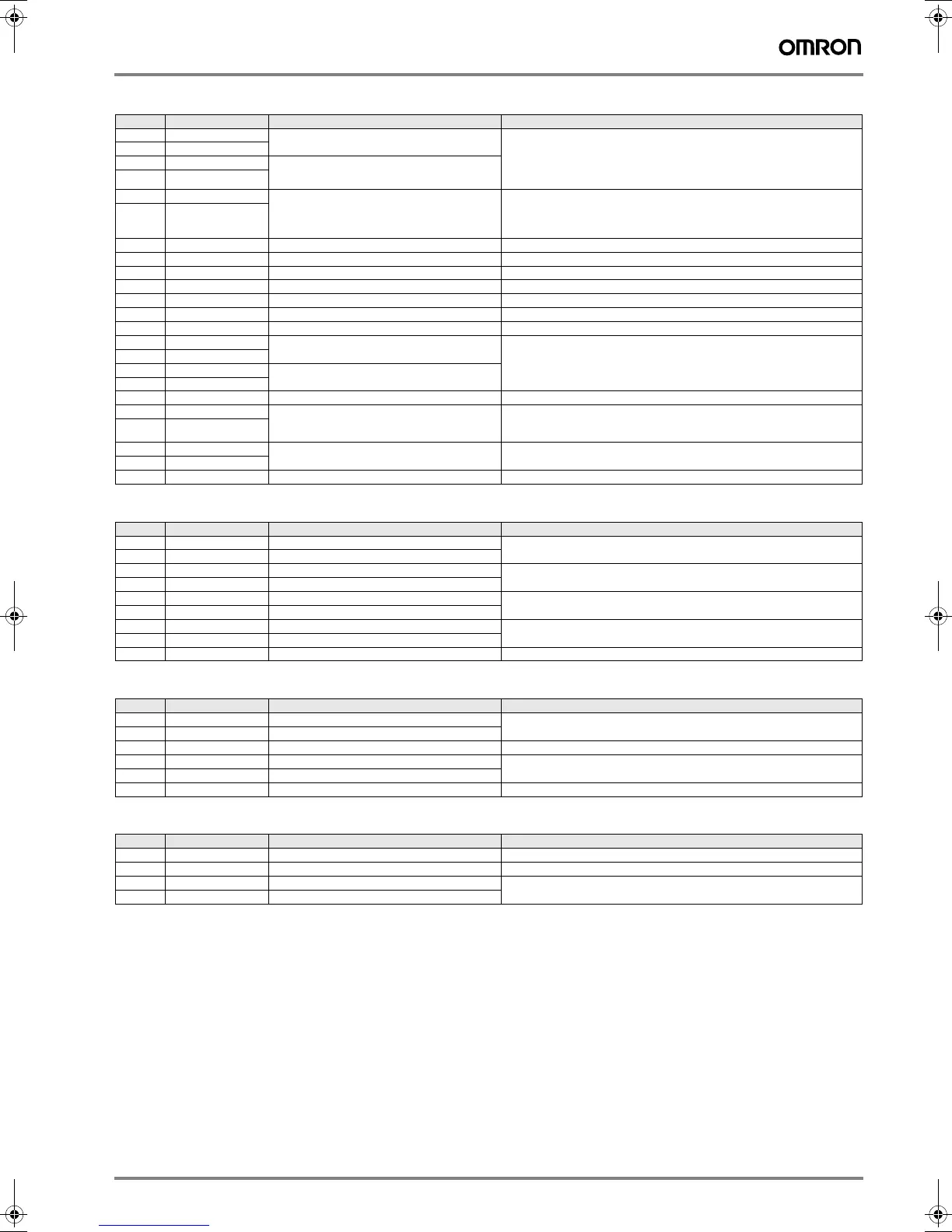
Control I/O (CN1) specifications
Encoder connector (CN2) specifications
Communications connector (CN3) specifications
Monitor output (CN4) specifications
Pin Symbol Name Function
1 +PULS/CW/A Feed pulses, reverse pulses,
or 90° phase difference pulses (A phase)
Line-driver input: 7 mA at 3 V
Open-collector input
Input impedance: 200 Ω
Maximum response frequency: 250 kpps
Position control is performed based on the pulses that have been input.
2 −PULS/CW/A
3 +SIGN/CCW/B Direction signal, forward pulses,
or 90° phase difference pulses (B phase)
4 −SIGN/CCW/B
5 +ECRST Deviation counter reset Line-driver input: 7 mA at 3 V
Open-collector input: 16 mA at 5 V
Input impedance: 200 Ω
ON: resets deviation counter.
6 −ECRST
7 BKIR Brake interlock output Outputs holding brake timing signals.
8 INP Positioning completed output ON when the position error is within the positioning completed range.
10 OGND Output ground common Ground common for output signals (pins 7 and 8).
13 +24V +24 VDC power input for control Power supply input (+24 VDC) for pins 14 and 18.
14 RUN RUN command input ON: servo ON (starts power to servo motor)
18 RESET Alarm reset input ON: servo alarm status is reset.
19 GND RS-422A ground Ground for RS-422A
20 RXD+ RS-422A reception data Interface for RS-422A data transfers
21 RXD−
22 TXD+ RS-422A transmission data
23 TXD−
24 RT Termination resistance terminal Connect to RXD- (pin 21) in the unit at the end of the line.
32 Z Encoder phase-Z open-collector output Output goes ON when the encoder’s phase-Z signal (1 pulse/revolution)
is detected.
Open-collector output: 20 mA max. at 30 VDC
33 ZCOM
34 ALM Alarm output Output goes OFF when alarm is detected.
Open-collector output: 50 mA max. at 30 VDC
35 ALMCOM
Shell FG Cable shield ground Ground for cable's shield wire.
Pin Symbol Name Function
1, 2, 3 E0V Encoder power supply GND Power supply output for encoder
4, 5, 6 E5V Encoder power supply +5 V
8 S+ Encoder + phase-S input Line driver input (conforms to EIA-RS422A)
(Input impedance: 220 Ω ± 5%)
9S− Encoder − phase-S input
10 A+ Encoder + phase-A input Line driver input (conforms to EIA-RS422A)
(Input impedance: 220 Ω ± 5%)
11 A− Encoder − phase-A input
12 B+ Encoder + phase-B input Line driver input (conforms to EIA-RS422A)
(Input impedance: 220 Ω ± 5%)
13 B− Encoder − phase-B input
Shell FG Cable shield ground Ground for cable's shield wire.
Pin Symbol Name Function
1 /TXD Transmission data Transmission data: RS-232C output
Reception data: RS-232C input
2 /RXD Reception data
3 PRMU Unit switching Switching terminal for a parameter unit
7 +5V +5 V output This is the +5 V power supply output to the parameter unit.
8 GND Ground
Shell FG Cable shield ground Ground for cable's shield wire.
Pin Symbol Name Function
1 NM Speed monitor Speed monitor output: 1 V per 1,000 r/min
2 AM Current monitor Current monitor: 1 V / rated torque
3 GND Ground Grounds for monitor output
4 GND Ground
Y203-EN2-02-Katalog.book Seite 155 Mittwoch, 24. Mai 2006 2:22 14
 Loading...