www.dadehpardazan.ir 88594014-15
2-15
Symbol Signal levelFunctionName
Se-
quence
9 Multi-function contact output (NO con-
dition)
Set by parameter H2-01 (during running). Contact output
(SPST-NO)
output
10 Multi-function contact output common
30 VDC, 1 A max.
250 VAC, 1 A max.
25 Multi-function output 1
Set by parameter H2-02 (zero speed Open collector out-
27 Multi-function output 1 common
detection). put
26 Multi-function output 2
Set by parameter H2-03 (agree output ref-
48 V, 50 mA max.
37 Multi-function output 2 common
erence detection).
18 Fault output (NO condition)
When fault occurs: Contact output
19 Fault output (NC condition)
Terminals 18 to 20: Closed
(SPDT)
20 Fault output common
Terminals 19 to 20: Open
30 VDC, 1 A max.
250 VAC, 1 A max.
Analog
output
21 Multi-function analog output 1 Set by parameter H4-01. (Output frequen-
cy: 0 to ±10 V/±100% frequency)
0 to ±10 VDC, 0 to
10 VDC, 2 mA
23 Multi-function analog output 2 Set by parameter H4-01. (Output current:
5 V/Inverter rated current)
max.
22 Multi-function analog output common Common for analog output.
---
40
For option
41
42
43
Note Multi-function inputs 1 to 5, multi-function contact outputs, and multi-function output 1 to 2 allow
selection of various functions by changing parameter settings. The settings shown in paren-
theses in the Function column for the multi-function inputs and multi-function contact outputs indi-
cate the default settings.
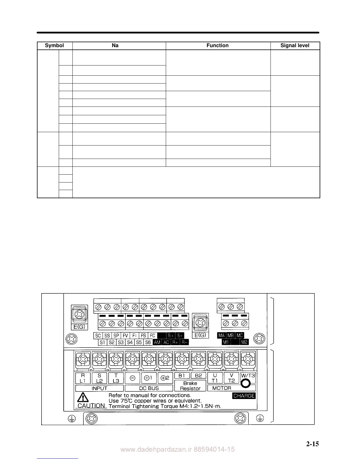
H 3G3HV Series
D Terminal Block Configuration (400-V Class with 3.7-kW Output, CUE Models)
Control
circuit
terminals
Main circuit
terminals
Installation Chapter 2