4-8SectionOffset and Gain Adjustment
99
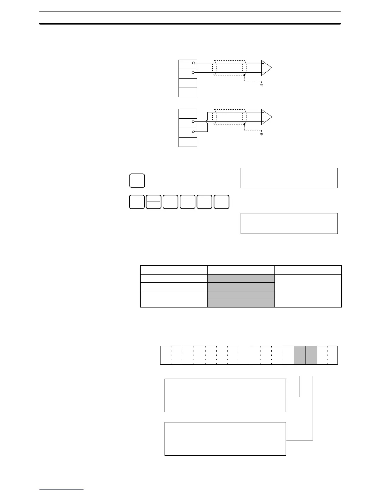
2. Check whether the output devices are connected.
A0
A1
A2
A3
A0
A1
A2
A3
Voltage output
Current output
Output 1
Output 1
3. Monitor IR word n+8 and check the set value while the Offset Bit is ON.
CLR
00000
SHIFT
CH
*
1
B
0
A
8
MONTR
c108
0000
4. Change the set value so that the output voltage and output current are as
shown in the following table. The data can be set within the indicated
ranges.
Output signal range Output voltage/current Output range
0 to 10 V 0 V
FF38 to 00C8
–10 to 10 V 0 V
1 to 5 V 1 V
4 to 20 mA 4 mA
Change the set value, using the Up Bit (bit 03 of word n+1) and the Down Bit
(bit 02 of word n+1).
15 14 13 12 11 10 09 08 07 06 05 04 03 02 01 00
Bit
Up Bit Down Bit
While the Up Bit is ON, the resolution will be
increased by 1 every 0.5 seconds. After it has
been ON for 3 seconds, the resolution will be
increased by 1 every 0.1 seconds.
While the Down Bit is ON, the resolution will be
decreased by 1 every 0.5 seconds. After it has
been ON for 3 seconds, the resolution will be
decreased by 1 every 0.1 seconds.
Word n+1