3
Unit no. IR word
0 100 through 109
1 110 through 119
2 120 through 129
3 130 through 139
4 140 through 149
5 150 through 159
6 160 through 169
7 170 through 179
8 180 through 189
9 190 through 199
Indicator panel There are two LEDs in the indicator panel, which function as follows:
Indicator Color Function
RUN Green Lit during normal operation. Unlit during errors.
BROKEN
WIRE
Red Lit when input is disconnected. Blinks when
data is outside of set range.
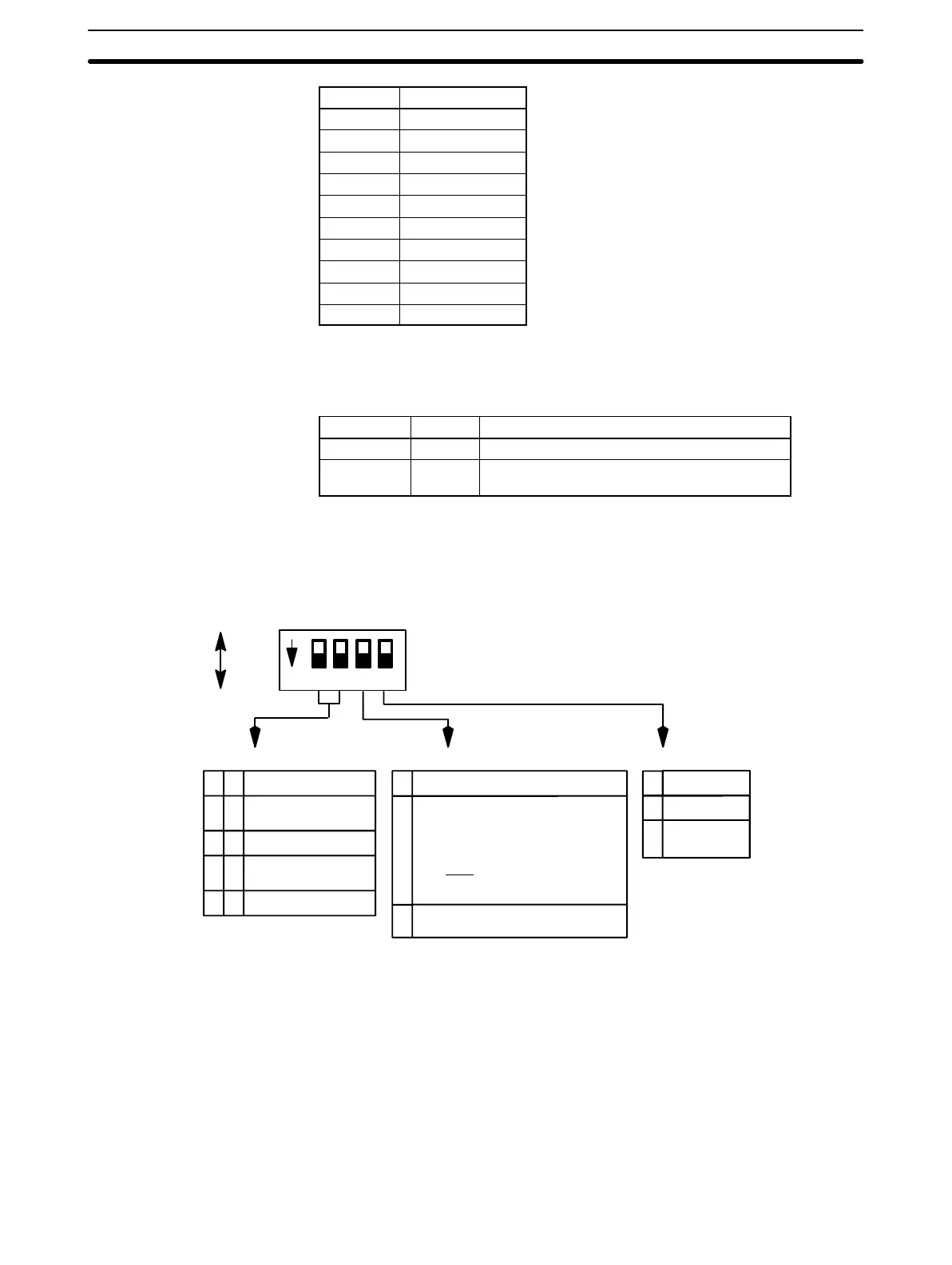
DIP Switch Setting
C200H-TS001/002
1234ON
2
0
1 No. of Input Points
0 0 4 input points (Inputs
1 through 4)
01
10
11
1 input point (Input 1)
2 input points (Inputs
1 and 2)
Not Used
3 Function
Either K (CA) (0° through 400°C), J
(IC) (0° through 300°C), or L (Fe-
CuNi) (0° through 300°C). Once this
pin has been set to ON, this setting
becomes invalid and the tempera-
ture must be set through the PC
program.
1 Set the temperature depending on
PC program.
4
0
1
Function
K ( CA)
J (IC), L(Fe-
CuNi)
OFF: 0
ON: 1
Number of Input Points Temperature Selector Sensor Selector
All switches are OFF before shipment from the factory.
The temperature specifications must be set identically for all four points.
These points cannot be used for different thermocouples or with different
temperature specifications.
The cold-junction compensating resistor connected to the C200H-TS001/002
terminal block (for the thermocouple) has been preset to the Unit’s internal
circuits. Do not remove or replace it. If it is necessary to remove it, when
reattaching, confirm that the number marked on the resistor matches the
number on the Unit, as shown in the following diagram. The output tempera-
ture data may be incorrect if the numbers do not match.
Nomenclature and Features Section 1-1