14
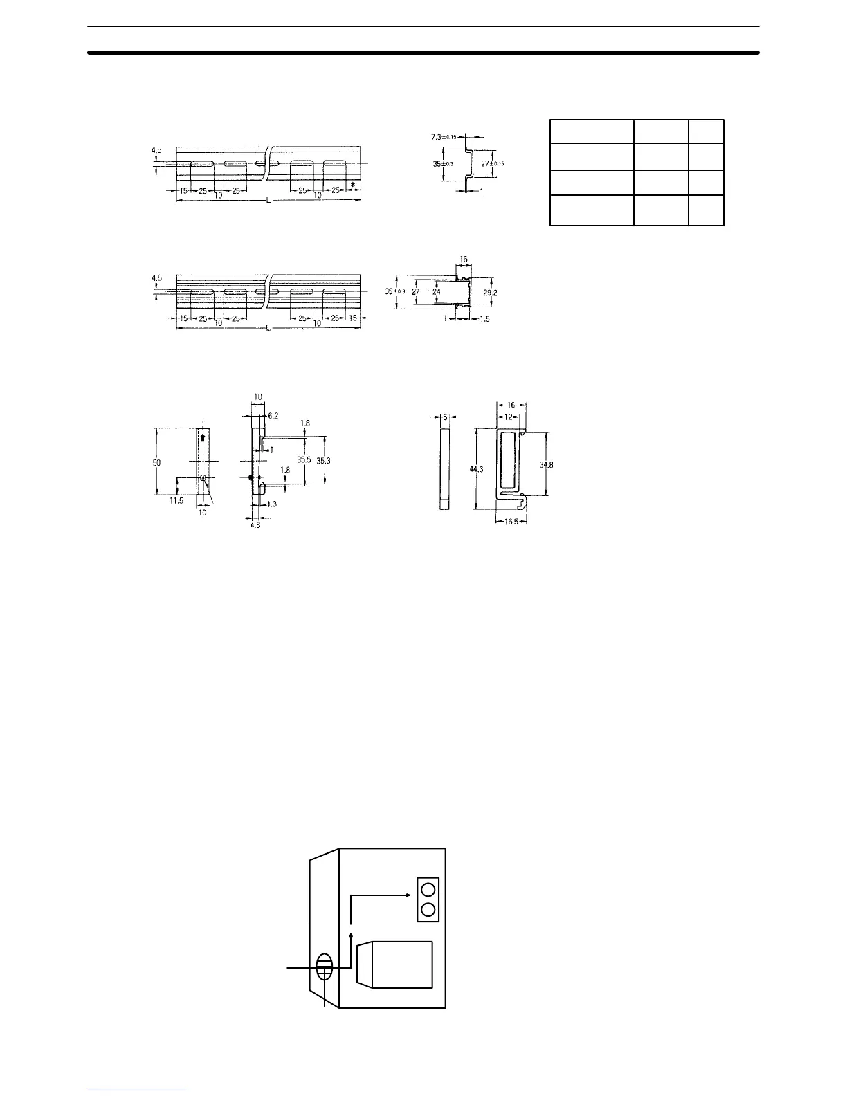
DIN Rails
*
5
15
––
Model
PFP–50N
PFP–100N
PFP–100N2
L
50 cm
1 m
1 m
* Use the PFP–100N2 for the C60P.
If the PFP–50N or PFP–100N are
used, the Unit will be slanted.
PFP–50N/PFP–100N
PFP–100N2
Endplate PFP–M
Eight M4
panhead
screws
Spacer PFP–S
Mounting A CPU and Expansion I/O Unit may be mounted either vertically or horizon-
tally in relation to each other but the orientation of each unit itself must re-
main horizontal as described by the following mounting diagrams. If mounting
the units vertically, position the CPU above the Expansion I/O Unit; if mount-
ing horizontally, position the CPU to the left.
When installing the CPUs, Expansion I/O Units, and I/O Link Units, allow suf-
ficient space between the Units for cooling. Models taking a 100– to
240–VAC power supply require a minimum cooling space of 10 mm between
Units. Avoid mounting any units in warm areas or over a heat source of any
kind.In addition, if the CPU is installed in a control box, allow sufficient space
for maintenence and ventilation. It may be necessary to install a ventilation
fan in the control box to maintain the required ambient temperature as indi-
cated in Appendix B Specifications.
Control Box
Fan
PC
Vent
Dimensions and Installation Section 2–3