80
I/O Memory Allocations Section 2-3
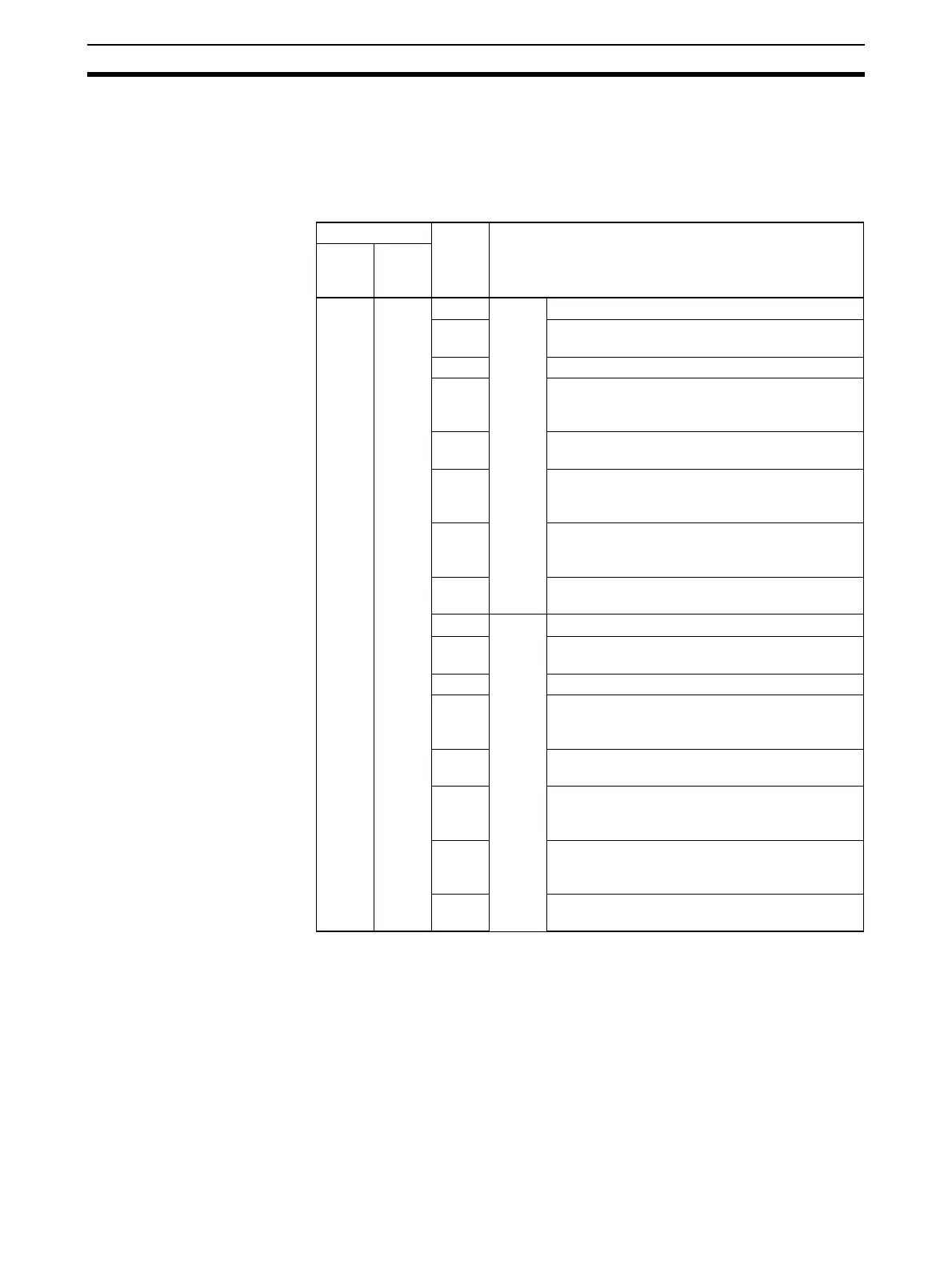
Software Switches Software Switches are used to output control signals from the CPU Unit to the
Serial Communications Board or Unit. The software switches are used for
loopback tests and to abort, release wait status, and control other functions
for protocol macros. For details on the software switch functions, refer to Sec-
tion 5 Using Protocol Macros and Section 10 Loopback Test.
n = CIO 1500 + 25
× unit number
Note The One-shot Trace Switch and Continuous Trace Switch are used for the
Serial Communications Board/Unit only when executing traces from the CX-
Protocol in protocol macro mode. Do not manipulate these switches from a
ladder diagram.
Status Area The Status Area is used for status information input from Serial Communica-
tions Board or Unit to the CPU Unit. The Status Area is where the Serial Com-
munications Board or Unit sets communications status, the transmission
control signal status, the transmission error status, and the protocol status.
Words Bit Function
Board
(CS
only)
Unit
(CS/
CJ)
CIO
1900
n 15 Port 2 Reserved
14 Loopback Test Switch (loopback tests)
1: Start, 0: Stop
13 Reserved
12 Serial Gateway Prohibited Switch (protocol mac-
ros)
1: Prohibited, 0: Not prohibited
11 Abort Switch (protocol macros)
1: Abort, 0: Aborted
10 One-shot Trace Switch (protocol macros, see
note)
1: Start, 0: Stop
09 Continuous Trace Switch
(protocol macros, see note)
1: Start, 0: Stop
08 Wait Release Switch (protocol macros)
1: Release wait, 0: Wait released
07 Port 1 Reserved
06 Loopback Test Switch (loopback tests)
1: Start, 0: Stop
05 Reserved
04 Serial Gateway Prohibited Switch (protocol mac-
ros)
1: Prohibited, 0: Not prohibited
03 Abort Switch (protocol macros)
1: Abort, 0: Aborted
02 One-shot Trace Switch (protocol macros, see
note)
1: Start, 0: Stop
01 Continuous Trace Switch
(protocol macros, see note)
1: Start, 0: Stop
00 Wait Release Switch (protocol macros)
1: Release wait, 0: Wait released
 Loading...


