Power supply input
Voltage input
(default setting)
Built-in In
h-speed counter 2 (phase-Z/reset
h-speed counter 1 (phase-Z/reset
h-speed counter 0 (phase-Z/reset
h-speed counter 2 (phase-A, increment, or count input
h-speed counter 2 (phase-B, decrement, or direction input
h-speed counter 1 (phase-A, increment, or count input
h-speed counter 1 (phase-B, decrement, or direction input
h-speed counter 0 (phase-A, increment, or count input
h-speed counter 0 (phase-B, decrement, or direction input
h-speed counter 3 (phase-A, increment, or count input
h-speed counter 3 (phase-B, decrement, or direction input
h-speed counter 3 (phase-Z/reset
in search function set to be used
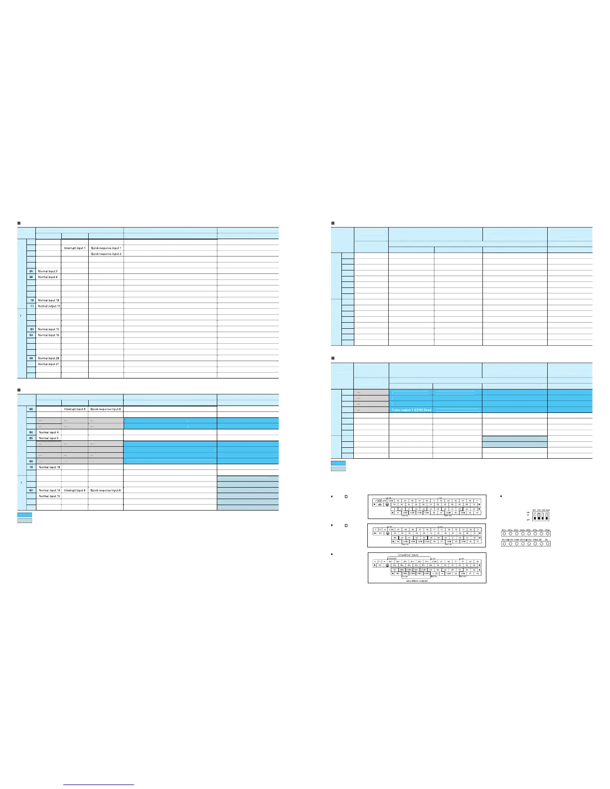
CP1H-X CPU Units
with AC power supply
Built-in Analog I/O Terminal Block Arrangement for
CP1H-XA CPU Units
CP1H-X CPU Units
with DC power supply
CP1H-Y CPU Units
Instructions
ut 0 (direction)
Pulse out
ut 1 (direction)
Pulse out
in search 0 (Error counter reset output
in search 1 (Error counter reset output
in search 2 (Error counter reset output
in search 3 (Error counter reset output
in search function is used
When the ori
in search function is used
in search 2 (Error counter reset output)
Ori
in search 3 (Error counter reset output)
Ori
in search 0 (Error counter reset output)
Ori
in search 1 (Error counter reset output)
In
These areas are for line-driver inputs, so they are can be used only for hi
h-speed counters (1 MHz) and not for other purposes, such as normal inputs
Pulse 0: Origin input signa
h-speed counter 2 (phase-Z/reset
h-speed counter 1 (phase-Z/reset) fixe
h-speed counter 0 (phase-Z/reset) fixe
h-speed counter 2 (phase-A, increment, or count input
h-speed counter 2 (phase-B, decrement, or direction input)
Hi
h-speed counter 1 (phase-A, increment, or count input) fixe
h-speed counter 1 (phase-B, decrement, or direction input) fixe
High-speed counter 0 (phase-A, increment, or count input) fixe
h-speed counter 0 (phase-B, decrement, or direction input) fixe
h-speed counter 3 (phase-A, increment, or count input) fixe
h-speed counter 3 (phase-B, decrement, or direction input) fixe
h-speed counter 3 (phase-Z/reset
h-speed counter operation settin
in search function set to be used.
Normal in
Origin search
These areas are for line-driver out
uts (1 MHz) and not for normal out
in search function is set to
be used in the PLC Setup, and an ori
in search function is set to
be used in the PLC Setup, and an ori
in
search is executed by the ORG instructio
CP1H CPU Unit Terminal Block Arrangemen

 Loading...


