20.4 to 26.4 VDC (21.6 to 26.4 VDC with four or more Ex
uts: 20 A max. 8 ms max./200 to 240 VAC in
between the external AC terminals
300 VAC at 50/60 Hz for 1 min between the external AC and
GR terminals, leaka
to IEC 61000-4-4. 2 kV (power supply line
litude, 57 to 150 Hz, acceleration: 9.8 m/s2 in X, Y, and Z directions for 80 minutes eac
time: 8 minutes x 10 swee
s = total time 80 minutes)
between the external DC terminals
000 VAC at 50/60 Hz for 1 min between the external DC and
GR terminals, leaka
AC power supply models: CP1H- -A
DC power supply models: CP1H-
: Serial PLC Link can be used with either serial
or the CP1W-CIF11 RS-422A/485 O
es: 0000 to 1770 (2EE0) he
Photocoupler isolation between analo
I/O terminals and internal circuits. No isolation between analo
orted (Set for individual in
orted (Value when disconnected: 8000 Hex
Cyclic scan with immediate refreshin
Approx. 400 (function codes: 3 di
clic tasks and 256 interru
Scheduled interrupt tasks: 1 (interrupt task No. 2, fixed)
In
t task No. 140 to 147, fixed), 6 for Y CPU Units
Hi
h-speed counter interrupt tasks: 256 (interrupt task No. 0 to 255
1,600 bits (100 words): CIO 0.00 to CIO 99.15 (The 24 built-in in
uts are allocated in CIO 0.00 to CIO 0.11 and CIO 1.00 to CIO 1.11.
1,600 bits (100 words): CIO 100.00 to CIO 199.15 (The 16 built-in out
uts are allocated in CIO 100.00 to CIO 100.07 and CIO 101.00 to CIO 101.07.
440 bits (90 words): CIO 3100.00 to CIO 3189.15 (CIO 3100 to CIO 3189
192 bits (512 words): W000.00 to W511.15 (W0 to W511
344 words): CIO 3800.00 to CIO 6143.15 (CIO 3800 to CIO 6143
192 bits (512 words): H0.00 to H511.15 (H0 to H511
rohibited): 7168 bits (448 words): A0.00 to A447.15 (A0 to A447
isters (16 bits): DR0 to DR1
isters (16 bits): IR0 to IR1
s (32 bits): TK0000 to TK0031
Trace Memor
les for the trace data maximum of 31 bits and 6 words.
Cassette A special Memory Cassette (CP1W-ME05M) can be mounted. Note: Can be used for pro
ram backups and auto-bootin
rams, parameters (such as the PLC Setup), comment data, and the entire DM Area can be saved to flash memory as initial values.
Battery backup: The Holdin
Area, DM Area, and counter values (fla
s, PV) are backed up by a battery
ansion (I/O) Unit x 7 Units
: 5 kHz max. for all interru
le-phase (pulse plus direction, up/down, increment), 100 kH
e: 32 bits, Linear mode or rin
et value comparison or ran
uts (models
with transistor out
ezoidal or S-curve acceleration and deceleration (Dut
uts, 1 Hz to 100 kHz (CCW/CW or
uts, 1 Hz to 30 kHz (CCW/CW or
PWM outputs :(Duty ratio: 0.0% to 100.0% (Unit: 0.1%)
uts, 0.1 to 1 kHz (Accurac
1 input (Resolution: 1/256, Input ran
ezoidal or S-curve acceleration and deceleration
(Dut
uts, 1 Hz to 1 MHz (CCW/CW or
2 outputs, 1 Hz to 30 kHz (CCW/CW or pulse plus direction
ratio: 0.0% to 100.0% (Unit: 0.1%)
uts, 0.1 to 1 kHz (Accurac
2 inputs: Differential phases (4x), 500 kHz or Sin
2 inputs: Differential phases (4x), 50 kHz or Sin
le-phase (pulse plus
direction, u
/down, increment), 100 kH
e: 32 bits, Linear mode or rin
et value comparison or ran
ansion (I/O) Unit x 7 Units)
6 in
: 5 kHz max.
for all interru
uts: Two axes for CW and CC
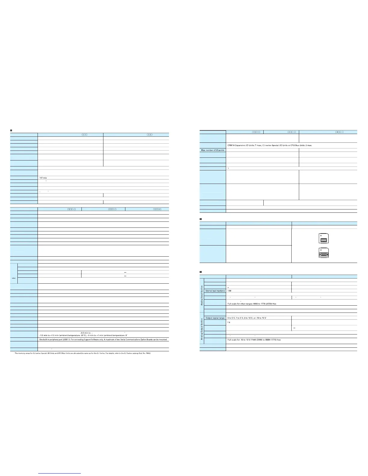
Analog I/O Specifications (CP1H-XA CPU Units Only
rotocol, NT Link (1: N), Serial PLC Link (See note.),
Serial Gatewa
/F master, Modbus-RTU master),
Modbus-RTU eas
rotocol, NT Link (1: N), Serial PLC Link (See note.),
Serial Gatewa
/F master, Modbus-RTU master),
Modbus-RTU eas

 Loading...


