EasyManuals Logo
Home>Omron>Controller>Sysmac CP1H

Omron Sysmac CP1H User Manual

Omron Sysmac CP1H
18 pages
To Next Page IconTo Next Page
To Previous Page IconTo Previous Page
Page #9 background imageLoading...
Page #9 background image
1
6
17
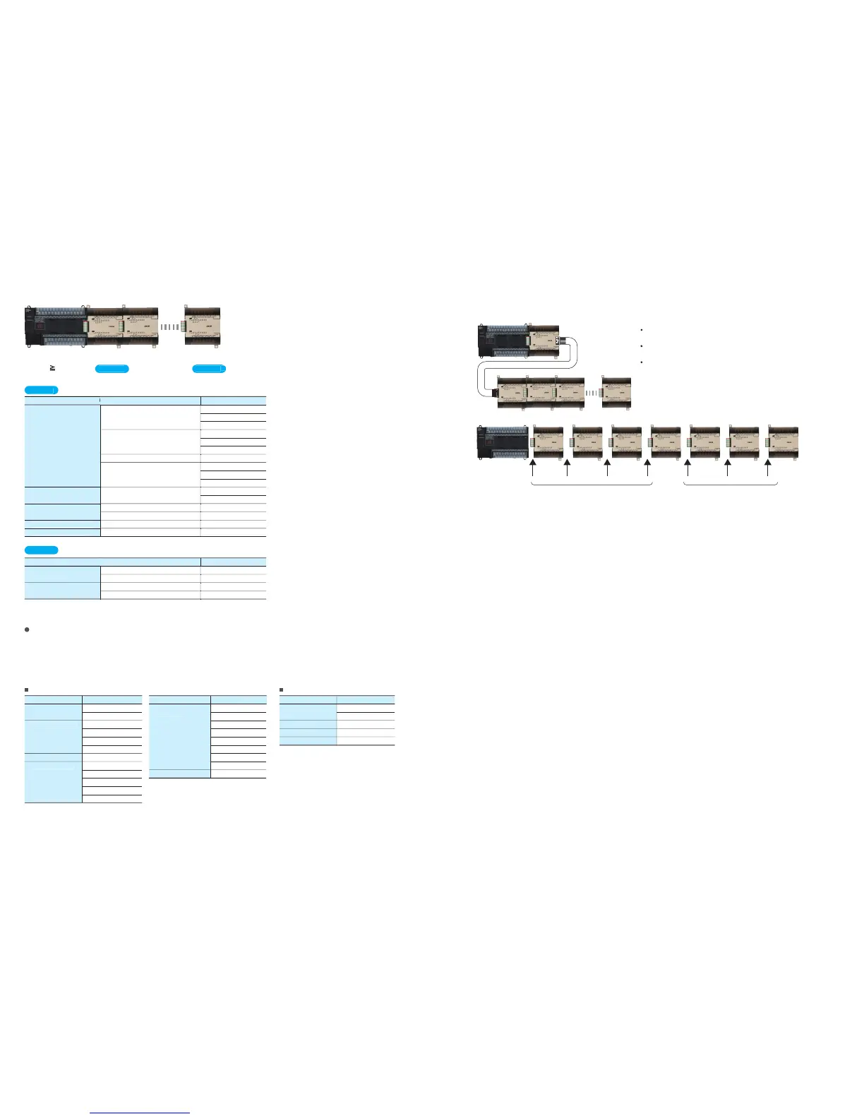
A maximum of seven CPM1A Expansion I/O Units can be connected, but the following restrictions apply.
7 Units Number of
group
A
Units + Number of
group
B
Units x 2
Can be used.
Expansion: 1st Unit 2nd Unit 3rd Unit 4th Unit 5th Unit 6th Unit 7th Unit
Cannot be used.
U
ni
ts
Cou
n
ted
in
t
h
e
Se
v
e
n
Co
nn
ectab
l
e
U
ni
ts
Precautions when Using CP1W-CN811 I/O Connecting Cable
Grou
p
A
U
ni
ts
t
h
at
E
ac
h
Cou
n
t
as
Tw
o
o
f
t
h
e
Se
v
e
n
Co
nn
ectab
l
e
U
ni
ts
Grou
p
B
CJ-series S
p
ecial I/O Units and CPU Bus Unit
s
U
U
nit t
ype
Ex
p
ansion I/O Unit
s
Analo
g
Uni
t
Tem
p
erature Sensor Unit
s
Com
p
oBus/S I/O Link Uni
t
DeviceNet I
/
O Link Uni
t
40 I/O
p
oint
s
2 analo
g
inputs,
1 analo
g
outpu
t
2 thermocou
p
le in
p
ut
s
2
p
latinum resistance thermometer in
p
ut
s
8 in
p
uts, 8 out
p
ut
s
32 in
p
uts, 32 out
p
uts
20 I/O
p
oint
s
8 in
p
ut
s
8 out
p
ut
s
C
PM1A-4
0
ED
R
C
PM1A-4
0
ED
T
C
PM1A-4
0
EDT
1
C
PM1A-2
0
EDR
1
C
PM1A-2
0
ED
T
C
PM1A-2
0
EDT
1
C
PM1A-
8
E
D
C
PM1A-
8
E
R
C
PM1A-
8
E
T
C
PM1A-
8
ET
1
C
PM1A-MAD
01
C
PM1A-MAD1
1
C
PM1A-T
S001
C
PM1A-T
S
1
01
C
PM1A-
S
RT2
1
C
PM1A-DRT2
1
M
odel
Unit t
ype
Analo
g
Unit
s
Tem
p
erature Sensor Unit
s
4 analo
g
input
s
4 analo
g
output
s
4 thermocou
p
le in
p
ut
s
4
p
latinum resistance thermometer in
p
ut
s
C
PM1A-AD
0
4
1
C
PM1A-DA
0
4
1
C
PM1A-T
S002
C
PM1A-T
S
1
02
M
odel
Maximum Number of Expansion Units That Can Be Connected
CJ-series S
p
ecial I/O Unit
s
CJ
-
se
ri
es
C
P
U
B
us
U
ni
ts
U
ni
t
n
a
m
e
M
odel
U
ni
t
n
a
m
e
M
odel
U
ni
t
n
a
m
e
M
odel
Analo
g
Input Unit
s
Analo
g
Output Unit
s
Analo
g
I/O Uni
t
Process In
p
ut Unit
s
C
J1W-AD
08
1-V
1
C
J1W-AD
0
41-V
1
C
J1W-DA
08V
C
J1W-DA
08C
C
J1W-DA
0
4
1
C
J1W-DA
0
2
1
C
J1W-MAD4
2
C
J1W-PT
S51
C
J1W-PT
S52
C
J1W-PT
S
1
5
C
J1W-PT
S
1
6
C
J1W-PD
C
1
5
Tem
p
erature
Co
n
t
r
o
l
U
ni
ts
Com
p
oBus/S Master Uni
t
C
J1W-T
C001
C
J1W-T
C002
C
J1W-T
C003
C
J1W-T
C004
C
J1W-T
C
1
01
C
J1W-T
C
1
02
C
J1W-T
C
1
03
C
J1W-T
C
1
04
C
J1W-
S
RM2
1
Se
ri
a
l
Co
mm
u
ni
cat
i
o
n
s
U
ni
ts
E
t
h
e
rn
et
U
ni
t
D
e
vi
ce
N
et
U
ni
t
Co
n
t
r
o
ll
e
r Link
U
ni
t
C
J1W-
SCU
41-V
1
C
J1W-
SCU
21-V
1
C
J1W-ETN2
1
C
J1W-DRM2
1
C
J1W-
C
LK21-V
1
For exam
p
le, if onl
y
Grou
p
B Units are used, a maximum of three Units can be connected. It would
then be
p
ossible to additionall
y
connect one Grou
p
A Unit and two CJ-series S
p
ecial I/O Units or
C
P
U
B
us
U
ni
ts.
A maximum of two CJ-series S
p
ecial I/O Units or CPU Bus Units can be
connected by usin
g
a CP1W-EXT01 CJ Unit Adapter. The number of Units
that can be used with the CP1H is as described below.
Use CP1W-CN811 I/O Connecting Cable when using CPM1A Expansion I/O Units at the same time
as a CJ Unit Adapter. In this situation the number of CPM1A Expansion I/O Units that can be
connected is sub
j
ect to the restrictions described above
.
I/O Connecting Cable can be used only between the CPU
Unit and the fourth Expansion I/O Unit.
Only one I/O Connecting Cable can be used in a single
configuration.
Even when I/O Connecting Cable is used, the above
restrictions on the number of connectable CPM1A Expansion
I/O Units still apply.

Questions and Answers:

Question and Answer IconNeed help?

Do you have a question about the Omron Sysmac CP1H and is the answer not in the manual?

Omron Sysmac CP1H Specifications

General IconGeneral
BrandOmron
ModelSysmac CP1H
CategoryController
LanguageEnglish

Related product manuals