EasyManuals Logo

Omron Sysmac CP1H User Manual

Omron Sysmac CP1H
18 pages
To Next Page IconTo Next Page
To Previous Page IconTo Previous Page
Page #12 background imageLoading...
Page #12 background image
22
23
I/O Specifications
I
tem
Input volta
ge
Max. switchin
g
capacit
y
2 A, 250 VAC (cos = 1), 2 A, 24 VDC 4 A/common)
5 VDC
,
10 m
A
100,000 o
p
erations (24 VDC
)
48,000 operations (250 VAC, cos = 0.4)
20,000,000 o
p
eration
s
1
5
m
s
m
a
x
.
1
5
m
s
m
a
x
.
Min. switchin
g
capacit
y
ON dela
y
OFF dela
y
Circuit confi
g
uratio
n
Se
rvi
ce
lif
e
o
f
rela
y
El
ect
ri
cal
M
ec
h
a
ni
cal
R
es
i
st
iv
e
l
oad
In
duct
iv
e
l
oad
24 VDC +10%/
/
/
15
%
A
pp
licable sensor
s
2-wir
e
se
n
so
r
s
In
p
ut im
p
edanc
e
3
.
3
k
3
.
0
k
4.7 k
In
p
ut curren
t
7.5 mA t
yp
ica
l
8.5 mA t
yp
ica
l
5 mA t
yp
ica
l
ON volta
ge
17.
0
VD
C
min
.
17.
0
VD
C
min
.
1
4.4 VD
C
min
.
OFF volta
g
e/curren
t
1 mA m
a
x.
at
5
.
0
VD
C
1 mA m
a
x.
at
5
.
0
VD
C
1
mA m
a
x.
at
5
.
0
VD
C
ON dela
y
2.
5
µ
s
m
a
x
.
50
µ
s
m
a
x
.
1
m
s
m
a
x
.
OFF dela
y
2.
5
µ
s
m
a
x
.
Circuit confi
g
uratio
n
50
µ
s
m
a
x
.
1
m
s
m
a
x
.
C
I
O
0
.
0
4
to
C
I
O
0
.1
1
C
I
O
0
.
00
to
C
I
O
0
.
03
a
n
d
C
I
O
1.
00
to
C
I
O
1.
03
C
I
O
1.
0
4
to
C
I
O
1.1
1
CIO 0.04
,
CIO 0.05
,
CIO 0.10
,
CIO 0.1
1
CP1H-XA/X CPU Unit
s
C
P1H-Y
C
P
U
U
ni
ts
C
I
O
0.00
,
CIO 0.01 and CIO 1.00 to CIO 1.0
3
CIO 1.04
,
CIO 1.0
5
S
p
ecification
s
S
p
ecification
s
I
tem
CP1H-XA
/
X CPU Unit
s
In
p
ut bits: CIO 0.04, CIO 0.06, CIO 0.08, CIO 0.10 (Phase A)
CIO 0.05
,
CIO 0.07
,
CIO 0.09
,
CIO 0.11 (Phase B)
CP1H-XA/X CPU Units
Input bits: CIO 0.00 to CIO 0.03, CIO 1.00 to CIO 1.03
CP1H-Y CPU Units
Input bits: CIO 0.00, CIO 0.11, CIO 1.00 to CIO 1.03
Input volta
ge
In
p
ut t
ype
In
p
ut curren
t
C
ir
cu
i
t
confi
g
uratio
n
ON/OFF dela
y
RS-422A line-driver, AM26LS31 or e
q
uivalent (See note.
)
Line-driver in
p
ut
10 mA t
yp
ica
l
13 mA t
yp
ica
l
N
ote
±
5
%
max
.
P
h
ase
Z
Hi
g
h-speed counter input
p
hases A and
B
I
tem
Hi
g
h-speed counter
in
p
ut
p
hase
Z
I
tem
Max. switchin
g
capacity
4.5 to 30 VDC: 300 mA/
p
oint, 0.8 A/common, 3.6 A/Unit (See notes 2 and 3.
)
Min. switchin
g
capacit
y
4.5 to 30 VDC
,
1 m
A
Leaka
g
e curren
t
0
.1 mA m
a
x
.
Residual volta
ge
0
.
6
V m
a
x
.
1.
5
V m
a
x
.
ON dela
y
0
.1 m
s
m
a
x
.
OFF dela
y
0
.1 m
s
m
a
x
.
1 m
s
m
a
x
.
F
use
1/
p
oint (See note 1.
)
Circuit confi
g
uratio
n
Item
Min. switching
capacity
Max. output
fre
q
uenc
y
Out
p
ut wavefor
m
S
p
ecification
s
30
mA
at
4.7
5
to
2
6
.4 VD
C
7 mA at 4.75
to 26.4 VDC
100 kHz
Sinkin
g
Output
s
Sourcin
g
Output
s
Sinkin
g
Output
s
Sourcin
g
Output
s
C
I
O
1
00
.
00
to
C
I
O
1
00
.
07
CIO 101.00
,
CIO 101.0
1
C
I
O
1
0
1.
0
2
to
C
I
O
1
0
1.
07
C
I
O
1
00
.
0
4
to
C
I
O
1
00
.
07
CP1H-XA
/
X CPU Unit
s
C
P1H-Y
C
P
U
U
ni
ts
CIO 101.00
,
CIO 101.0
1
CIO 101.02
,
CIO 101.0
3
S
p
ecification
s
Input volta
ge
In
p
ut im
p
edanc
e
In
p
ut curren
t
ON voltag
e
S
p
ecification
s
24 VDC +10%/
/
/
15
%
4.7 k
5 mA t
yp
ica
l
14.1 VD
C
min
.
5
.
0
VD
C
m
a
x
.
0 to 32 ms max.
(
Default: 8 ms
)
(
See note 1.
)
0 to 32 ms max.
(
Default: 8 ms
)
(
See note 1.
)
OFF volta
ge
ON dela
y
OFF dela
y
Circuit confi
g
uratio
n
Output waveform
Max.
output
frequency
I
tem
M
a
x.
ca
p
acit
y
Max. switchin
g
capacity
PWM
out
p
ut
p
recisio
n
1k Hz
30
mA
at
4.7
5
to
2
6
.4 VD
C
ON duty +5%, –0%
at out
p
ut fre
q
uenc
y
o
f 1 kH
z
Max.
output
fre
q
uenc
y
Item
Pulse
outputs
Max.
output
current
Circuit configuration
Specifications
Line-driver outputs,
Am26LS31 or
equivalent
20 mA
1 MHz
N
ote
:
I
tem
Max. switchin
g
ca
p
acit
y
(See note 2.)
Leakage current
Residual volta
ge
ON dela
y
S
p
ecification
s
C
PM1A-4
0
ED
T
C
PM1A-4
0
EDT
1
C
PM1A-2
0
ED
T
C
PM1A-2
0
EDT
1
0.1 mA max.
1.
5
V m
a
x
.
0
.1 m
s
m
a
x
.
0.1 mA max.
1.
5
V m
a
x
.
0
.1 m
s
m
a
x
.
0.1 mA max.
1.
5
V m
a
x
.
0
.1 m
s
m
a
x
.
1 m
s
m
a
x.
at
24 VD
C
+10%/
/
/
5%
,
5 to 300 m
A
1 m
s
m
a
x.
at
24 VD
C
+10%/
/
/
5%
,
5 to 300 m
A
+10%/
/
/
5%
,
5 to 300 m
A
N
o
n
e
1
/
commo
n
OFF dela
y
Fuse
(
See note 1.
)
Circuit confi
g
uration
C
PM1A-
8
E
T
C
PM1A-
8
ET
1
0.9 A/common
3.6 A/common
0.9 A/common
1.8 A/common
0.9 A/common
1.8 A/common
4.
5
to
30
VD
C
:
0.3 A/
p
oin
t
4 VDC +10%/
/
/
5
%
:
0.3 A/
p
oin
t
OUT00/OUT01: 0.2 A/
p
oint at 4.5 to 30 VDC
OUT02 to OUT07: 0.3 A/
p
oint at 4.5 to 30 VDC
I
tem
I
tem
Max. switchin
g
capacit
y
Min. switchin
g
capacit
y
Service
lif
e
o
f
rela
y
M
ec
h
a
ni
cal
R
es
i
st
iv
e
l
oad
In
duct
iv
e
l
oad
S
p
ecification
s
2 A, 250 VAC (cos = 1), 2 A, 24 VDC 4 A/common)
5 VDC
,
10 m
A
150,000 o
p
erations (24 VDC
)
100,000 operations (240 VAC, cos = 0.4)
20,000,000 o
p
eration
s
1
5
m
s
m
a
x
.
1
5
m
s
m
a
x
.
ON dela
y
OFF dela
y
Circuit confi
g
uratio
n
330
330
+
560
6800
pF
1
80
+
300
500
2
00
1
00
3
2
1
0
0
.1
0
.2
0
.
3
0
.
5
0
.7 1 2
3
5
1
0
12
5
VA
C
r
es
i
st
iv
e
l
oad
30 VDC = 7 ms
4
250 VAC cos = 0.4
Contact current
(
A
)
Internal
circuits
In
te
rn
a
l
c
ir
cu
i
ts
OUT
24 VD
C
4.
5
to
30
VD
C
COM
(
)
COM(–)
L
L
24 VD
C
4.
5
to
30
VD
C
Internal
circuits
Internal
c
ir
cu
i
ts
COM
(
+
)
COM(+)
L
L
In
te
rn
a
l
circuits
OUT
OUT
24 VDC
4.5 to 30 VDC
L
L
Internal
circuits
24 VDC
4.5 to 30 VDC
OUT
OUT
L
L
CWn+
CWn–
CCWn+
CCWn–
COM
(
)
OUT
24 VDC
/
4.5
to
30
VD
C
24 VDC
/
4.5
Sinkin
g
Output
s
In
te
rn
a
l
c
ir
cu
i
ts
L
L
Sinkin
g
Output
s
Out
p
ut LE
D
OUT
In
te
rn
a
l
c
ir
cu
i
ts
L
L
L
L
0
.
9
0
.
8
0
0
50
55
300
2
00
1
00
50
30
20
5
3
2
10
Contact current
(
A
)
L
ife
(
x10
4
)
Switchin
g
fre
q
uenc
y
:
1,
800
op
erations/
h
In
p
ut S
p
ecification
s
Output Specification
s
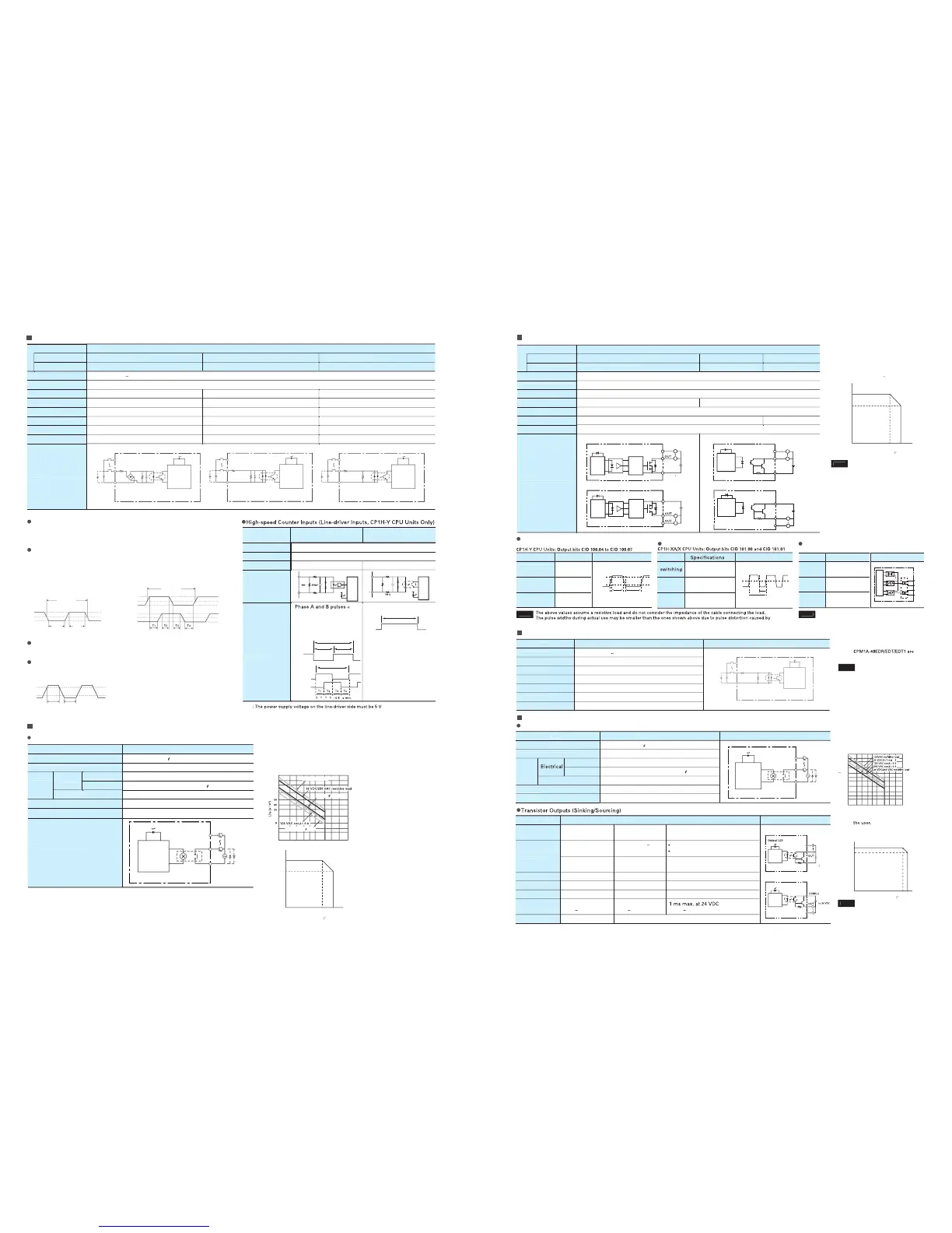
CPU Units with Transistor Outputs (Sinking/Sourcing
)
In
p
ut S
p
ecification
s
for CPM1A-40EDR
/
40EDT
/
40EDT1
/
20EDR1
/
20EDT
/
20EDT1
/
8E
D
Out
p
ut S
p
ecification
s
CPU Units with Relay Out
p
ut
s
IN
IN
IN
IN
IN
IN
COM
COM COM
3
.
3
k
3.0 k
4.7 k
2.4 k
910
750
1000pF
1000pF
Input LE
D
In
p
ut LE
D
In
p
ut LE
D
Internal
circuits
Internal
circuits
Internal
circuits
Out
p
ut LED
In
te
rn
a
l
c
ir
cu
i
ts
Maximum
250 VAC: 2 A
,
24 VD
C
: 2
A
OUT
COM
OUT
ON
90%
50%
10%
OFF
10.0 µs min.
2.5 µs
min.
2.5 µs
min.
ON
90%
10%
OFF
50 µs min. 50 µs min.
Under the worst conditions, the service life of out
p
ut contacts is
as
s
h
o
wn
o
n
t
h
e
l
e
f
t
.
The service life of relays is as shown in the followin
g
dia
g
ram
as a
g
uideline
.
47
0
0
55
3
4
ON
O
F
F
90
µ
s
min
.
1 µs min.
2
µ
s
min
.
Ph
ase
A
Ph
ase
B
1
,
2
,
3
,
4
µ
0
.
5
µs min. 0.5 µs min.
ON
O
F
F
ON
O
F
F
ON
O
F
F
ON
90
%
50
%
10
%
90
%
50
%
10
%
ON
OFF
OFF
Phase A
Phase B
20.0 µs min.
T1, T2, T3, T4: 2.5 µs min.
In
te
rn
al
c
ir
cu
i
ts
In
te
rn
al
c
ir
cu
i
ts
0.1 0.2 0.3 0.5 0.7 1 2 3 5 1
0
Internal circuits
0
.
9
0
.
6
0
0
50
55
In
te
rn
a
l
c
ir
cu
i
ts
In
te
rn
a
l
c
ir
cu
i
ts
COM
OUT
IN
IN
COM
OUT
Out
p
ut LE
D
In
p
ut LE
D
4.7
k
750
OFF
ON
ON duty
T
tON
ON 90%
10%
OFF
2
µ
s min.
4
µ
s min.
CP1H-Y CPU Units
Input bits: CIO 0.04, CIO 0.10 (Phase A)
CIO 0.05, CIO 0.11 (Phase B)
Co
mm
o
n
te
rmin
a
l
cu
rr
e
n
t
(
A
)
Ambient temperature
(
°
C
)
direction in
p
ut mode,
incrementin
g
mode,
acceleration
/
deceleration
p
ulse in
p
ut mode: 1-MHz
p
ulse with dut
y
ratio of 50
%
N
ote
1: Fuses cannot be re
p
laced b
y
the
use
r.
2: D
o
n
ot
use
m
o
r
e
t
h
a
n
0
.
9
A
tota
l f
o
r
C
I
O
1
00
.
00
to
C
I
O
1
00
.
3.
3: A maximum of 0.9 A
p
er common
ca
n
be
s
wi
tc
h
ed
at
a
n
a
m
b
i
e
n
t
tem
p
erature of 5
0
°
C
.
N
ote
1: Can be set in the PLC Setu
p
to 0,
0.5. 1
,
2
,
4
,
8
,
16
,
or 32 ms. The
fix
ed
at
1
6
m
s.
Under the worst conditions
,
the service life
o
f out
p
ut contacts is as shown on the left.
The service life of rela
y
s is as shown in the
followin
g
dia
g
ram as a
g
uideline
.
N
ote
1: The fuses cannot be re
p
laced b
y
2: A maximum of 0.9 A
p
er
co
mm
o
n
ca
n
be
s
wi
tc
h
ed
at
a
n
ambient tem
p
erature of 5
0
°C
Do not apply a volta
g
e or connect a load to
an output terminal exceedin
g
the maximum
switchin
g
capacity.
N
ote
:
Do not apply a volta
g
e exceedin
g
the
rated volta
g
e to an input terminal.
N
ote:
connectin
g
cable impedance.
N
ote
:
Connect a load of 20 mA or less to the out
p
ut. The
Unit may be dama
g
ed is a current of more than 20
mA is out
p
ut.
Co
mm
o
n
te
rmin
a
l
cu
rr
e
n
t
(
A
)
Ambient tem
p
erature
(
°
C
)
Pulse Out
p
ut
s
Rela
y
Out
p
uts (CPM1A-40EDR/20EDR1/8ER
)
CP1H-XA/X CPU Units: Out
p
ut bits CIO 100.00 to CIO 100.07
Pulse Out
p
ut
s
Pulse Outputs (Line-driver Outputs)
CP1H-Y CPU Units
Co
mm
o
n
te
rmin
a
l
cu
rr
e
n
t
(
A
)
A
mbient tem
p
erature
(
°
C)
Note:
Do not apply a volta
g
e or connect a load
to an output terminal exceedin
g
the
maximum switchin
g
capacity
.
Pulse plus direction input mode
Increment mode
Up/down input mode

Questions and Answers:

Question and Answer IconNeed help?

Do you have a question about the Omron Sysmac CP1H and is the answer not in the manual?

Omron Sysmac CP1H Specifications

General IconGeneral
BrandOmron
ModelSysmac CP1H
CategoryController
LanguageEnglish

Related product manuals