er of the indicated value
er of the indicated value
oints (TS001, TS101); 250 ms/4
data with resolution of 6,00
Full scale for -10 to 10 V: F448
es: 0000 to 1770 (2EE0) he
between isolated circuits)
Dielectric stren
500 VAC for 1 min (between isolated circuits
Photocoupler isolation (between analog inputs
an
Supported (Set for each input usin
1/256 (1/512 for output si
8-bit binary with sign bi
Binary data (hexadecimal, 4 di
Binary data (hexadecimal, 4 di
Binary data with resolution of 6,00
Full scale for -10 to 10 V: F448
es: 0000 to 1770 (2EE0) he
Photocoupler isolation between analo
internal circuits. No isolation between
analo
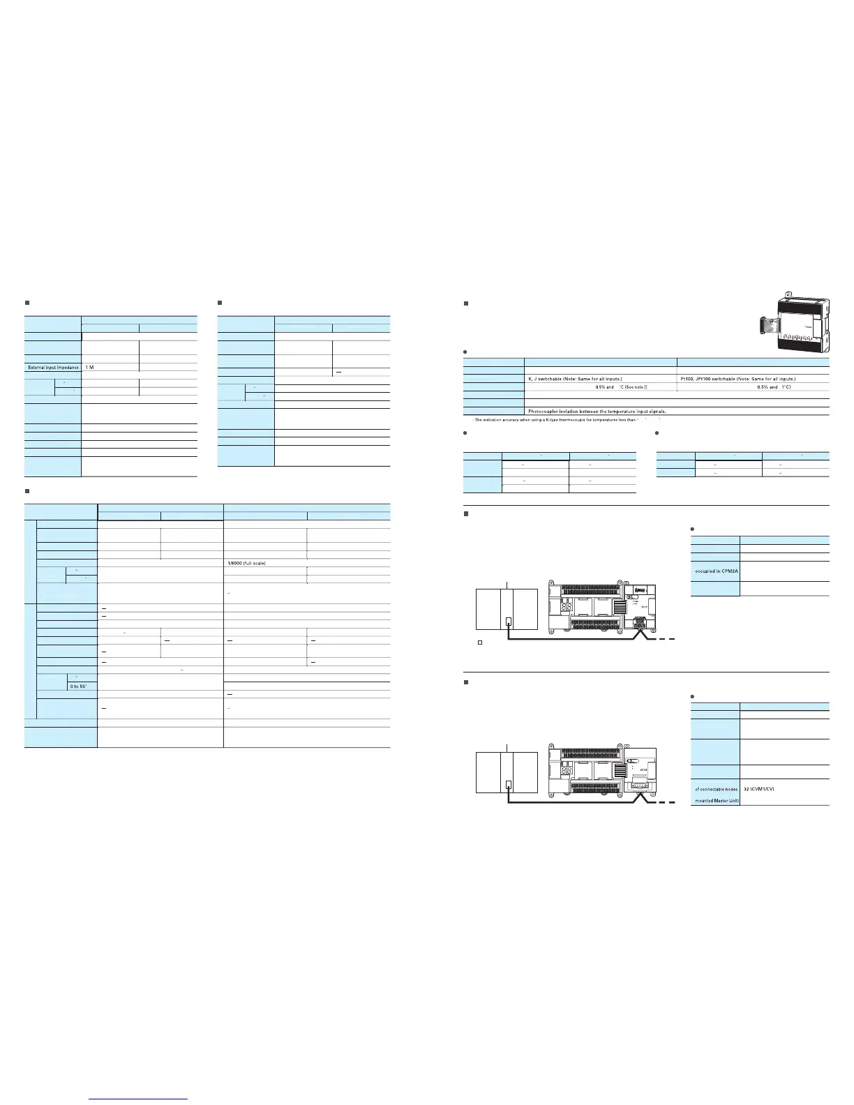
By mounting a Temperature Sensor Unit to the PLC, inputs can be obtained from thermocouples
or platinum resistance thermometers, and temperature measurements can be converted to
binary data (4-di
it hexadecimal) and stored in the input area of the CPU Unit
The CompoBus/S I/O Link Unit functions as a slave for a CompoBus/S
Master Unit (or an SRM1 Com
oBus/S Master Control Unit) to form an
I/O Link with 8 inputs and 8 outputs between the CompoBus/S I/O Link
Unit and the Master Unit.
N
(Allocated in the same wa
before the CPU Unit is turned ON
(Allocated in the same wa
as for
other Expansion Units.
DIP switch
(before CPU Unit is
CompoBus/S Master Unit
(or SRM1 CompoBus/S
Master Control Unit)
A maximum of 16 Units can be connected
(or 8 Units for CQM1-SRM21-V1).
CPM1A-SRT21
CompoBus/S I/O
Link Unit
CP1H
Special flat cable or VCTF cable
CS/CJ Series
C200H Series
CQM1 (H) Series
SRM1 Series
CPM2C-S Series
DeviceNet Master Unit
A m
(when CS1 Master Units are used).
CPM1A-DRT21
DeviceNet I
CP1H
CS/CJ Series
C200HX/HG/HE/HS Series
CV/CVM1 Series
Analog Input Uni
Expansion I/O
Analog I/O Unit
CPM1A-TS001/TS002/TS101/TS102
Temperature Sensor Units
RT21
CompoBus/S I/O Link Unit
By connecting a CPM1A-DRT21 DeviceNet I/O Link Unit, a CPM2A can
function as a slave for a DeviceNet Master Unit to establish I
O links for
32 inputs and 32 outputs between the CPM2A and the Master Unit.
CPM1A-DRT21
DeviceNet I/O Link Unit
Output Section (See note 1.)
Photocou
ler isolation between I/O terminals and PLC
si
nals (There is no isolation between the analo
Photocoupler isolation between analo
I/O and internal circuits (There
is no isolation between the analo
e output and current output can be used at the same time for analo
outputs, but the total output must not exceed 21 mA.2: The conversion time is the total time for 2 analo
2: The conversion time is the total time for 2 analo
Input Temperature Ranges for CPM1A-TS001/002
(The rotary switch can be used to make the followin
Input Temperature Ranges for CPM1A-TS101/10
(The rotary switch can be used to make the followin
e and
input type settings.

 Loading...


