4 - 21
4 Installation and Wiring
NX-series Communications Interface Units User’s Manual (W540)
4-4 Wiring Communications
4
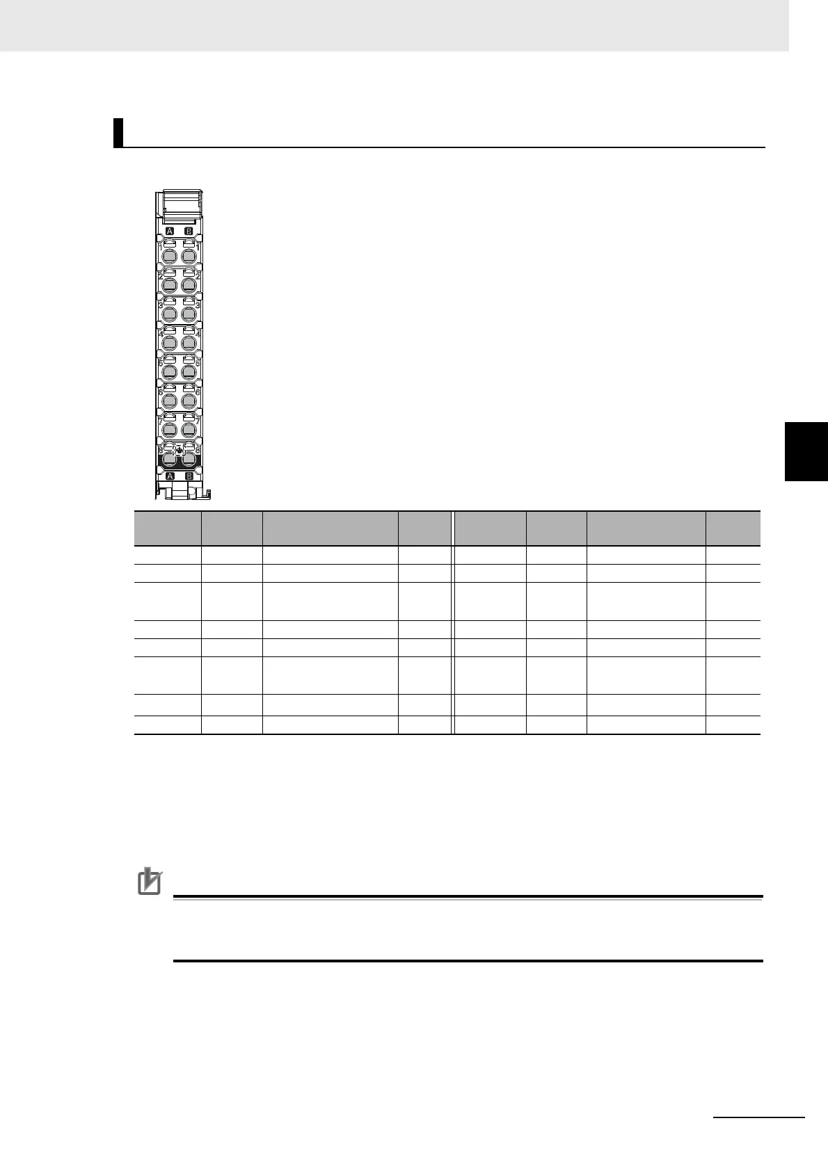
4-4-1 Terminal Arrangement
The terminal arrangement of the NX-CIF105 is given below.
Precautions for Correct Use
If you use the RS-422A/485 port, check the polarity before you connect the cable. The polarity
of the SDA/SDB and RDA/RDB terminals and signals are reversed for some remote devices. If
the polarity is not correct, malfunctions may occur.
NX-CIF105 Terminal Arrangement
Terminal
No.
Abbrev. Signal name I/O
Terminal
No.
Abbrev. Signal name I/O
A1 SDA- Send data - Output B1 SDB+ Send data + Output
A2 SDA- Send data - Output B2 SDB+ Send data + Output
A3 TER
SDA-
Terminal send data -
*1
*1. For a two-wire connection, terminating resistance is turned ON when TERSDA- is connected to TERSDB+.
--- B3 TER
SDB+
Terminal send data
+
*1
---
A4 RDA- Receive data - Input B4 RDB+ Receive data + Input
A5 RDA- Receive data - Input B5 RDB+ Receive data + Input
A6 TER
RDA-
Terminal receive data
-
*2
*2. For a four-wire connection, terminating resistance is turned ON when TERRDA- is connected to TERRDB+.
--- B6 TER
RDB+
Terminal receive
data +
*2
---
A7 SG
Signal ground
*3
*3. The SG terminals are internally connected to the 0-V line inside the Unit. It is normally not necessary to con-
nect the SG terminals. However, it may be possible to increase noise immunity by connecting the communi-
cations cables to the SG terminals.
--- B7 SG Signal ground ---
A8 FG Frame ground --- B8 FG Frame ground ---
A1
A2
A3
A4
A5
A6
A7
A8
B1
B2
B3
B4
B5
B6
B7
B8