4 - 27
4 Installation and Wiring
NX-series Communications Interface Units User’s Manual (W540)
4-4 Wiring Communications
4
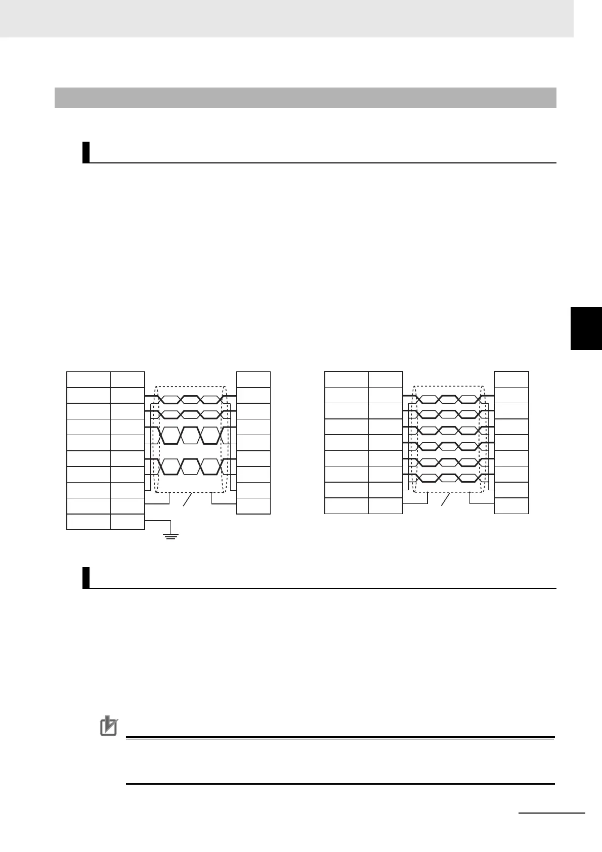
4-4-3 Examples of Recommended RS-232C and RS-422A/485 Wiring
This section provides examples of the recommended RS-232C and RS-422A/485 wiring.
We recommend the following wiring for RS-232C communications, particularly in environments where
noise is
common.
• Use shielded, twisted-pair cable for the communications cable.
• Pair the SD (send data) line with the SG (signal ground)
line as one twisted pair and the RD (receive
data) line with the SG (signal ground) line as a separate twisted pair.
• For the NX-CIF210, connect the shield on the communications cable to the shell (SHLD) on the
D-Sub con
nector on the NX-CIF210. Also, ground the ground terminal (GR) on the Power Supply
Unit to 100 or less.
• For the NX-CIF101, connect the shield on the communic
ations cable to A6 (SHLD) on the
NX-CIF101. Also, ground the A8 (FG) on the NX-CIF101 to 100 or less.
Connection examples are given in the following figure.
For RS-422A/485, we recommended that you use the follow
i
ng wiring method to ensure transmission
quality.
• Use shielded, twisted-pair cable for the communications cable.
• Connect the shield on the communications cable to A8 or
B8 (FG) on the NX-CIF105. Also, ground
the A8 or B8 (FG) on the NX-CIF101 to 100 or less.
• Always turn ON the terminating resistance at the
end nodes for RS-422A/485 communications. To
turn ON the terminating resistance, connect TERSDA- and TERSDB+ for a two-wire connection and
connect TERRDA- and TERRDB+ for a four-wire connection.
Precautions for Correct Use
Ground the shield only at the CIF Unit. Do not ground it at the other end of the cable. If you
ground both ends of the cable, a difference in electrical potential between the two grounds may
damage the equipment.
4-4-3 Examples of Recommended RS-232C and RS-422A/485 Wiring
Examples of Recommended RS-232C Wiring
Examples of Recommended RS-422A/485 Wiring
Shield
Serial communications
device
Shield
Serial communications
device
Pin No.
2
3
4
6
7
8
5
Shell
NX-CIF210
NX-CIF210
Ground the ground terminal (GR) on
the Power Supply Unit to 100 Ω or less.
NX-CIF101
Signal
RD
SD
ER
DR
RS
CS
SG
SHLD
Signal
SD
RD
DR
ER
CS
RS
SG
FG
Terminal No.
B1
A1
A3
B3
A2
B2
A4
A6
A8
NX-CIF101
Signal
RD
SD
ER
DR
RS
CS
SG
SHLD
FG
Signal
SD
RD
DR
ER
CS
RS
SG
FG