8
Product-specic cautions
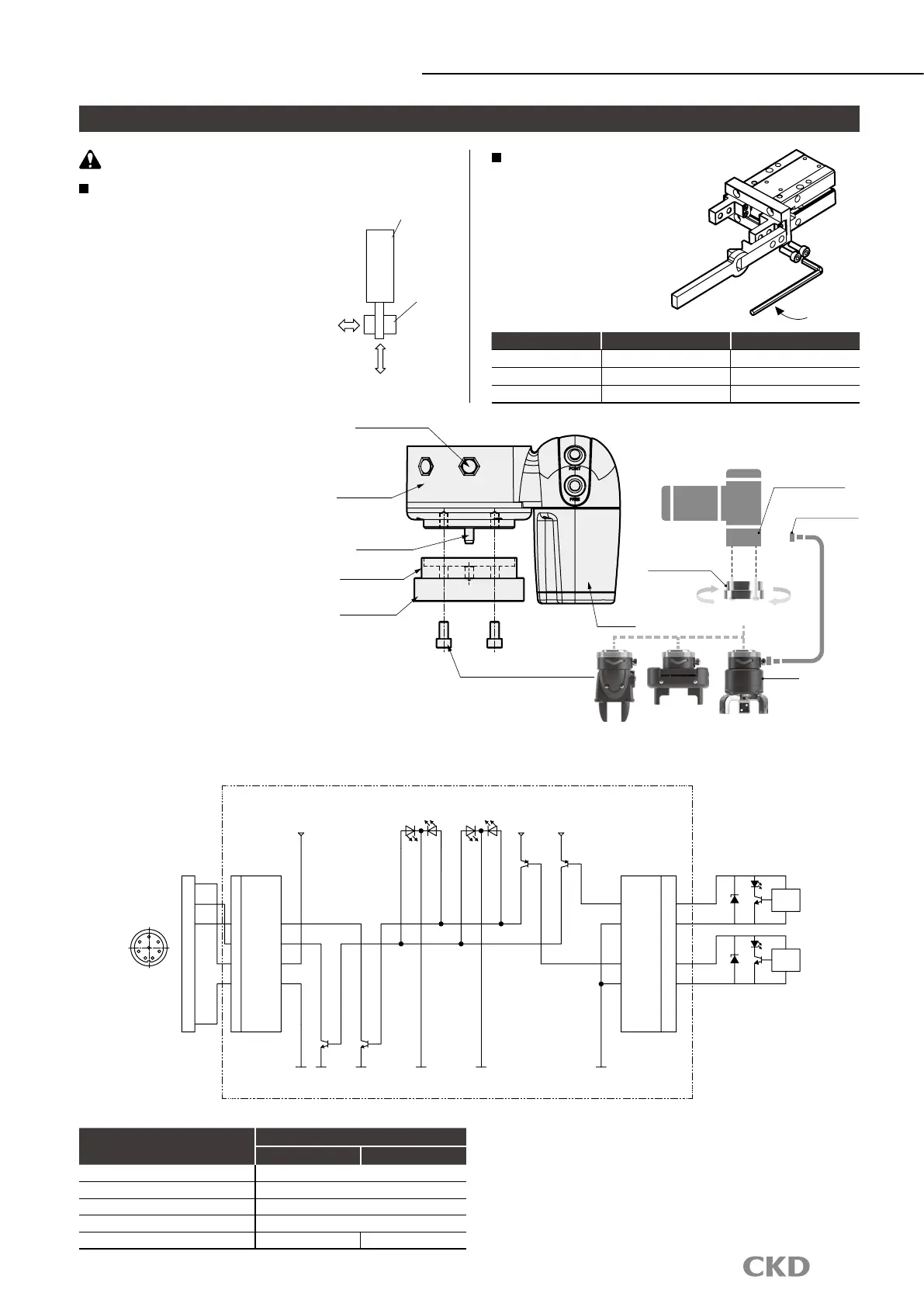
Grippers for collaborative robots
Mounting, installation and adjustment
CAUTION
Do not apply excessive load to
the nger or attachment when
attaching/removing or transporting
the workpiece. Scratches and
dents may occur on the rolling
surface of the nger linear guide,
possibly causing malfunction.
Item Bolt used
Tightening torque (N
・
m)
RLSH-A20D1N M4 × 0.7 1.4
RHLF-16CS M4 × 0.7 1.4
RCKL-40CS M5 × 0.8 2.8
Mounting the attachment
When mounting the attachment
to the nger, to prevent any
effect on the gripper, support
with a wrench, etc., when
tightening so that the nger is
not twisted.
[Electric circuit diagram]
[Mounting method]
(1) When mounting the gripper, keep the
LED lamp parallel to the camera. Mount
the parallel pin on the connector side.
(2) Loosen the clamp ring and remove the
robot ange from the gripper.
After inserting the parallel pin (included)
on the robot ange side, mount the
robot ange to the robot with 4 hexagon
socket head cap screws (included).
Note: Tightening torque = 7 N・m
(3) Mount the gripper on the robot ange
and tighten the clamp ring.
Note: Turn the clamp ring forcefully by
hand to tighten it, and check that
it is not loose.
(4) Connect the gripper connector to the
robot tool connector.
[Switch specications]
Item
Proximity 2-wire
F2H T2H
Applications Dedicated for programmable controller
Load voltage/current 10 to 30 VDC 5 to 20 mA
Leakage current 1 mA or less
Impact resistance 980 m/s
2
Weight g 10 18
Do not apply load to
the body.
Tightening
Gripper
Workpiece
Wiring connector
Tool connector
Robot ange
Gripper
Tool connector
Robot side
Parallel pin
Camera
Robot ange
Clamp ring
Hexagon socket head cap screw 4 pcs
Flange inner indicator lamp
Flange inner cylinder switch
Tool I/O connector
24V
LED1
blue bluegreen green
GND GNDGNDGNDGNDGND
LED2
24V 24V
WH
BN
GN
YE
GY
PK
BU
RD
1
2
3
4
5
6
7
8
1
2
3
SW2 OUT
4
SW1 OUT
5 24V IN
6 GND IN
7
8
9
SW1 OUT
10
SW1 GND
11
12
SW2 OUT
13
SW2 GND
14
15
16
Load fail
Load fail
CN1 CN2
BN
SW-F2H (RLSH)
SW-T2H (RHLF)
SW-T2H (RCKL)
SW-F2H (RLSH)
SW-T2H (RHLF)
SW-T2H (RCKL)
Switch
Main circuit
Switch
Main circuit
BN
BU
BU
21
7 3
8
6 4
5

 Loading...


