5
Grippers for collaborative robots
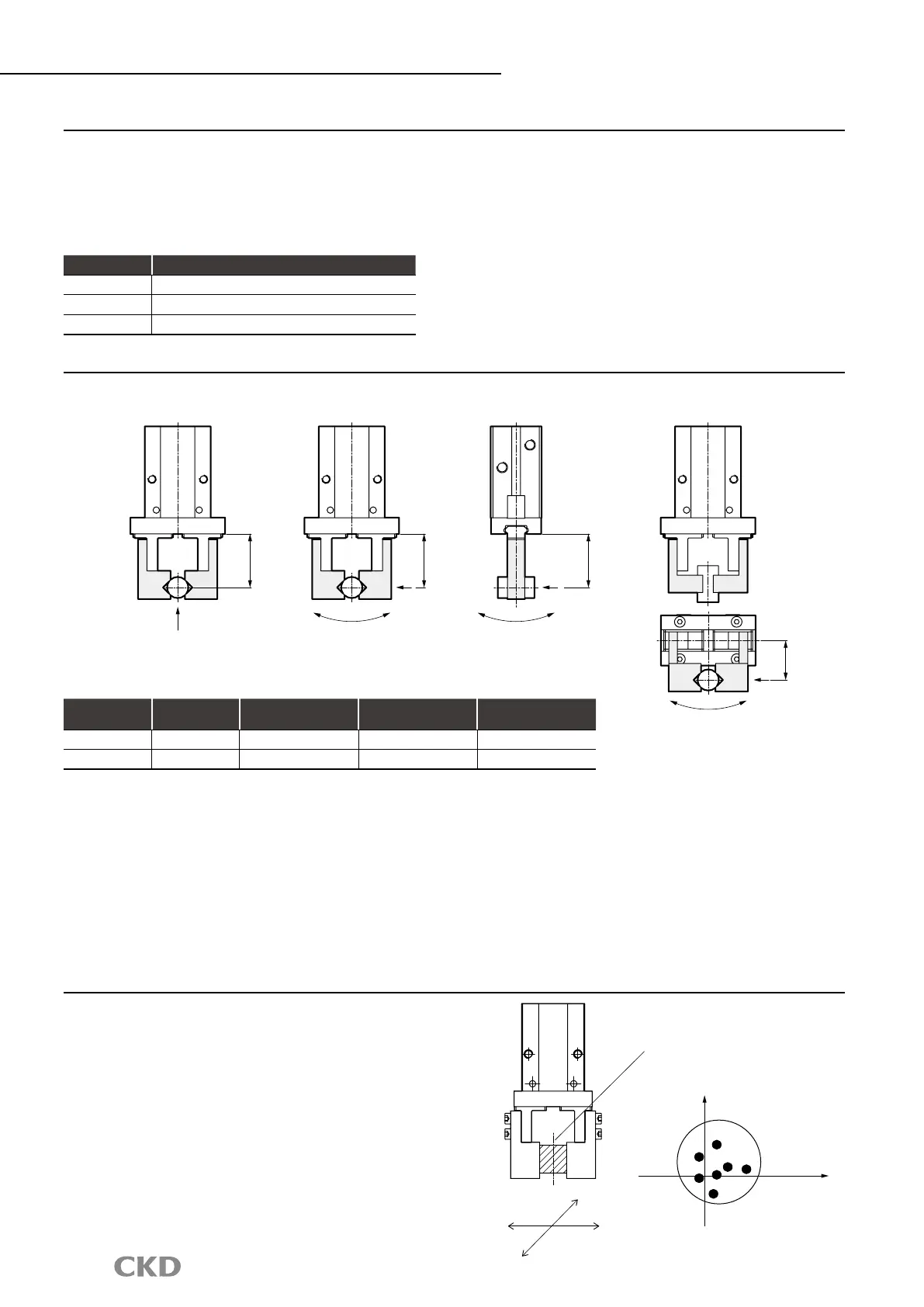
L: Distance to the point where load is applied
Attachment
External forces applied to nger
Repeatability
●
Use an attachment as short and lightweight as possible. If the attachment is long and heavy, inertia increases when opening
and closing. This may cause play in the nger, and adversely affect durability.
●
When mounting an L-shaped attachment, select length as shown below.
Ex.: If the L-shape is 30 mm in the nger direction and 30 mm at a 90° angle, assume the attachment length is 60 mm.
●
Length of attachment should be within the numerical values of gripping power performance data.
●
The weight of the attachment affects durability, so check that the weight is in accordance with the table below.
When external force such as workpiece transport or insertion is applied to the nger, use it within the range in [Table 1].
(*For use during transport, be careful of impacts applied to the end.)
・
Calculation example of external forces applied to nger
Calculation example (1): Workpiece transport
When gripping a workpiece (weight m = 0.7 kg, center of gravity distance L = 40 mm) with model No. RLSH-A20D1N, attachment
(weight m
k
= 0.4 kg, center of gravity distance L
k
= 30 mm) for transport
(When g: gravity acceleration = 9.8 m/s
2
and α: coefcient of impact on end = 3)
M
1
= α × W
1
× L=α × (m
k
× g × L
k
× 2 + m × g × L)
= 3 × (0.4 × 9.8 × 30 × 10
−3
× 2 + 0.7 × 9.8 × 40 × 10
−3
) ≈ 1.5 N
・
m, M
1
max = 1.8 N
・
m or less, use is possible
Calculation example (2): Workpiece insertion
Model No.: RLSH-A20D1N, where load W
1
of 30 N is applied to L: 40 mm
M
1
=W
1
×L = 30×40×10
−3
=1.2 N
・
m, M1
max
=1.8 N
・
m or less, use is possible
[Table 1] Allowable load value
Model
Vertical load
Wmax (N)
Bending moment
M1max (N
・
m)
Radial moment
M2max (N
・
m)
Torsion moment
M3max (N
・
m)
RLSH 198 1.8 3.6 1.8
RHLF 164 0.94 2 1.1
Model Weight W per attachment
RLSH W < 80 g
RHLF W < 100 g
RCKL W < 95 g
The repeatability here indicates the displacement of the workpiece
in the case of repeated clamping and unclamping in the same
conditions (gripper xed, same workpiece used: see right).
Conditions
・
Workpiece dimensions, shape, weight
・
Workpiece transfer position
・
Clamp method, length
・
Workpiece and workpiece receiving surface resistance
・
Fluctuation of gripping power (air pressure), etc.
Base line
●
: Base line
X
X
Y
Y
L
L
L
L
Vertical load
W (N)
Bending moment
M1 (N
・
m) = W1 × L
Radial moment
M2 (N
・
m) = W2 × L
Torsion moment
M3 (N
・
m) = W3 × L
W1
W2
W3

 Loading...


