7
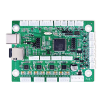
3.4.1 Control Board Power
On the control board, find the largest 4 pin terminal. Connect the “PWR” terminal block previously removed from
your old board to this terminal. If you are connecting the wires individually for a new or different system, connect
the pin marked “24V” to your engraver’s 24V power supply and the pin marked “GND” to the power supply’s
ground port, sometimes marked “0V”.
3.4.2 Laser Tube Connection
This control board does not directly connect to your laser tube.
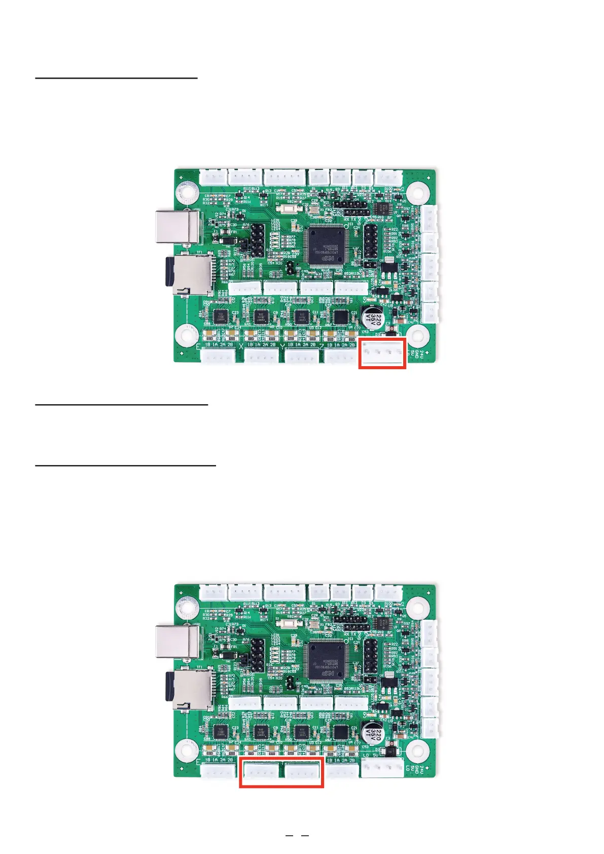
3.4.3 Laser Head Connections
On the control board, find the 4 pin terminals marked “X” and “Y” beside the power terminal just connected. Connect
the “X” and “Y” terminal blocks previously removed from your old board to these terminals. If you are connecting
the wires individually for a new or different system, bipolar stepper motors will use the same four pin terminals.
Connect the two wires coming from either coil to the pins marked “1A” and “1B”. Connect the two wires from the
other coil to the pins marked “2A” and “2B”.