The 5 pin terminals marked “X” and “Y” in the center of the board might be necessary for some upgraded stepper
motors. You can connect them directly to a preassembled terminal or wire them separately. Connect each pin
marked “5V” to the positive pins (“PUL+”, “DIR+”, and “EN+”) for the corresponding axis. Connect each pin
marked “GND” to the corresponding ground (“GND” or “0V”) pin. Connect the pins marked “STP”, “DIR”, and
“EN” to the corresponding negative pulse (“PUL−”), direction (“DIR−”), and enable (“EN−”) pins respectively.
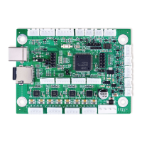
3.4.4 Device Input Connections
This circuit board can accept two separate 5V input signals from devices such as an interlock open cover sensor or
a foot-controlled power switch. (If your engraver did not come with an interlock sensor, it is strongly recommended that
you install such a sensor.) You can connect preassembled 3 pin terminal blocks to the central terminal across from
the USB and microSD card ports or wire them separately. Connect the live wire to either of the outer pins (“IN1”
or “IN2”) and connect the grounds to the central pin (“GND”).
8