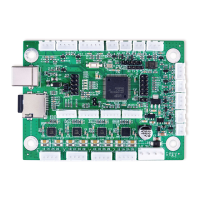
The 2 and 3 pin thermistor terminals (“TH1”–“TH5”) can provide similar 5V inputs from CNC thermistors or other
sensors. Each accepts one or two input lines and a ground line (“GND”) between or to the right.
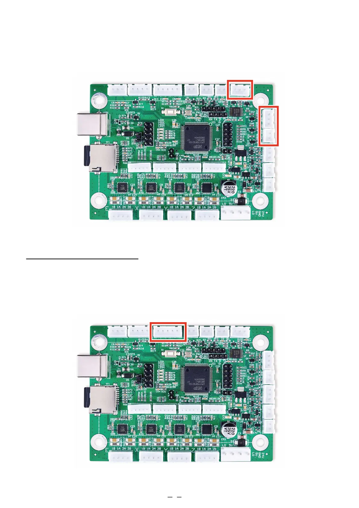
3.4.5 Limit Switch Connections
On the control board, find the 5 pin terminal along the side next to the USB port. Connect the “END” or “LMT” terminal
block previously removed from your old board to this terminal. If you are connecting the wires individually for a new or
different system, connect the pin marked “Y−” to your Y axis limit switch. Connect the pin marked “X−” to your X axis
limit switch. Connect the “GND” pins to the ground connections for the corresponding limit switch.
9