10
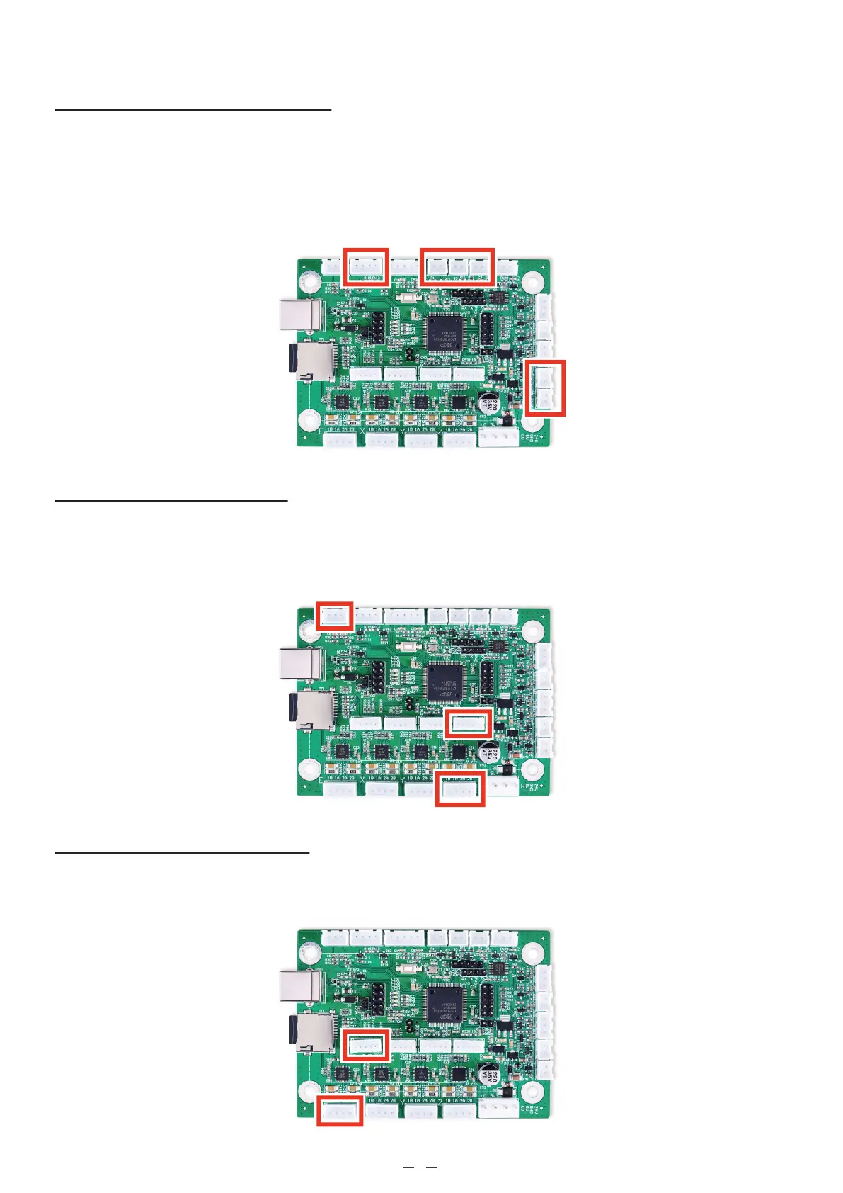
3.4.6 Device Output Connections
This circuit board can provide a 5V power feed and up to nine 5V output signals to control various ancillary devices
such as external exhaust fans, pressurized air assists, and CNC heating elements. The power feed terminal has 2 pins
for the current (“5V”) and the ground (“GND”). The output signal terminals accept 2, 3, or 4 pin terminal blocks and
are variously labelled “FAN”, “BLOW”, "HE1” and “HE2”, and “OUT1” and “OUT2”. Each has a line pin and a
shared or separate ground pin (“GND”).
3.4.7 Workbed Connections
To install an automatically adjustable workbed for your engraver, follow the instructions in §3.4.3 to connect its
stepper motor to either the outer 4 pin terminal or the inner 5 pin terminal marked “Z”. Connect its limit switches
to the “Z+”, “GND”, and “Z−” pins in the corner terminal next to the USB port.
3.4.8 Rotary Axis Connections
To install a rotary axis, follow the instructions in §3.4.3 to connect its stepper motor to either the outer 4 pin terminal or
the inner 5 pin terminal marked “E”.