Here, “PWR” is used for the main power input, “Y” and “X” for the motor drivers, and “END” for the limit switches.
Any clear phrasing is fine. If your old board already has other connections in addition to these, use its manual or
the board’s markings and the diagram in §1.5 to label those wires as well. Once all connected wires are clearly
labeled, disconnect them from the old board.
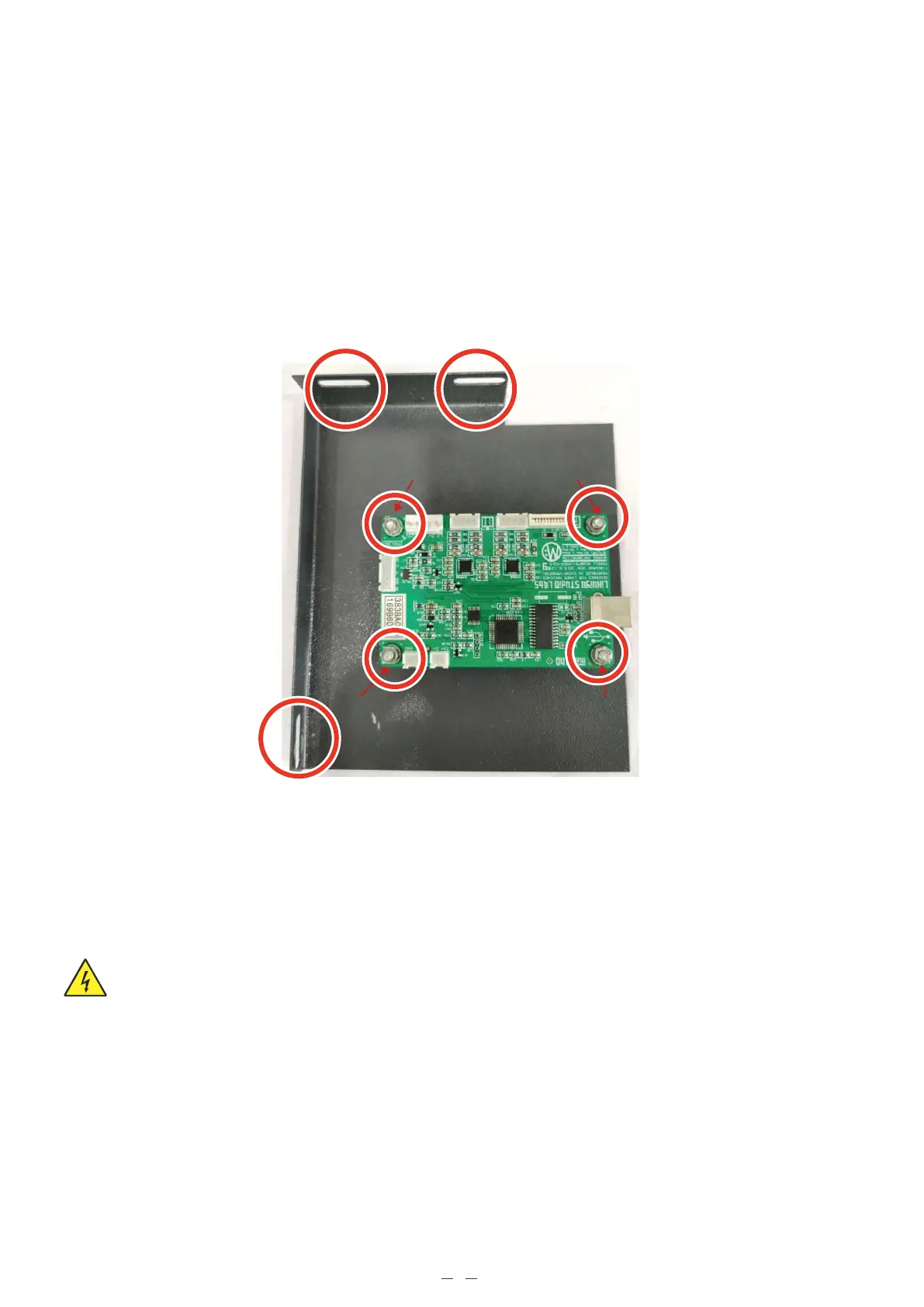
3.3 Replacing the Old Control Board
Remove the three bolts holding the control board plate to your engraver. Remove the plate and remove the four
bolts at the corners of the old control board.
You can mount the new control board into place now (being careful to position its USB port beside your casing’s
access hole) or make all the necessary electrical connections first before bolting it into place.
3.4 Electrical Connections
Only install this board while your engraver and all components are turned off and disconnected from power.
Always check that the polarities of your connections are correct, with a multimeter if needed.
6