130 v. no v. • «isn
r
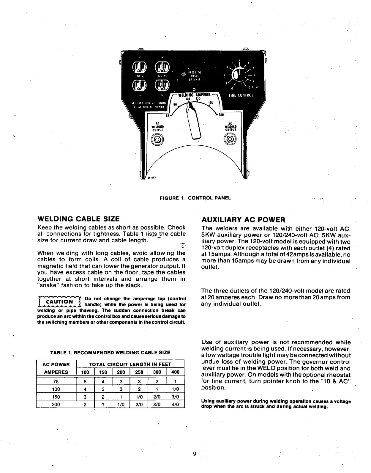
FIGURE 1. CONTROL PANEL
WELDING
CABLE
SIZE
Keep the welding cables as short as possible. Check
all connections for tightness. Table 1 listsJhe cable
size for current draw and cable length.
When welding with long cables, avoid allowing the
cables to form coils. A coil of cable produces a
magnetic field that can lower the generator output. If
you have excess cable on the floor, tape the cables
together at short intervals and arrange them in
"snake" fashion to take up the slack.
CAUTION
Do not change the amperage tap (control
handle) while the power is being used for
welding or pipe thawing. The sudden connection break can
produce an arc within the control box and cause serious damage to
the switching members or other components in the control circuit.
AUXILIARY
AC
POWER
The welders are available with either 120-volt AC,
5KW auxiliary power or 120/240-volt AC, 5KW aux-
iliary power. The 120-volt model is equipped with two
120-volt duplex receptacles with each outlet (4) rated
at
1
Samps.
Although a total of 42amps isavailable, no
more than 15amps may be drawn from any individual
outlet.
The three outlets of the 120/240-volt model are rated
at 20 amperes each. Draw no more than 20 amps from
any individual outlet.
TABLE 1. RECOMMENDED WELDING CABLE SIZE
AC POWER
AMPERES
TOTAL CIRCUIT LENGTH IN FEET AC POWER
AMPERES 100 150
200 250 300
400
75 6
4
3
3 2 1
100 4 3 3
2
1
1/0
150 3 2 1 1/0
2/0 3/0
200 2
1
1/0 2/0 3/0
4/0
Use of auxiliary power is not recommended while
welding current is being used. If necessary, however,
a low wattage trouble light may be connected without
undue loss of welding power. The governor control
lever must be in the WELD position for both weld and
auxiliary power. On models with the optional rheostat
for fine current, turn pointer knob to the "10 & AC"
position.
Using auxiliary power during welding operation causes a voltage
drop when the arc is struck and during actual welding.
 Loading...
