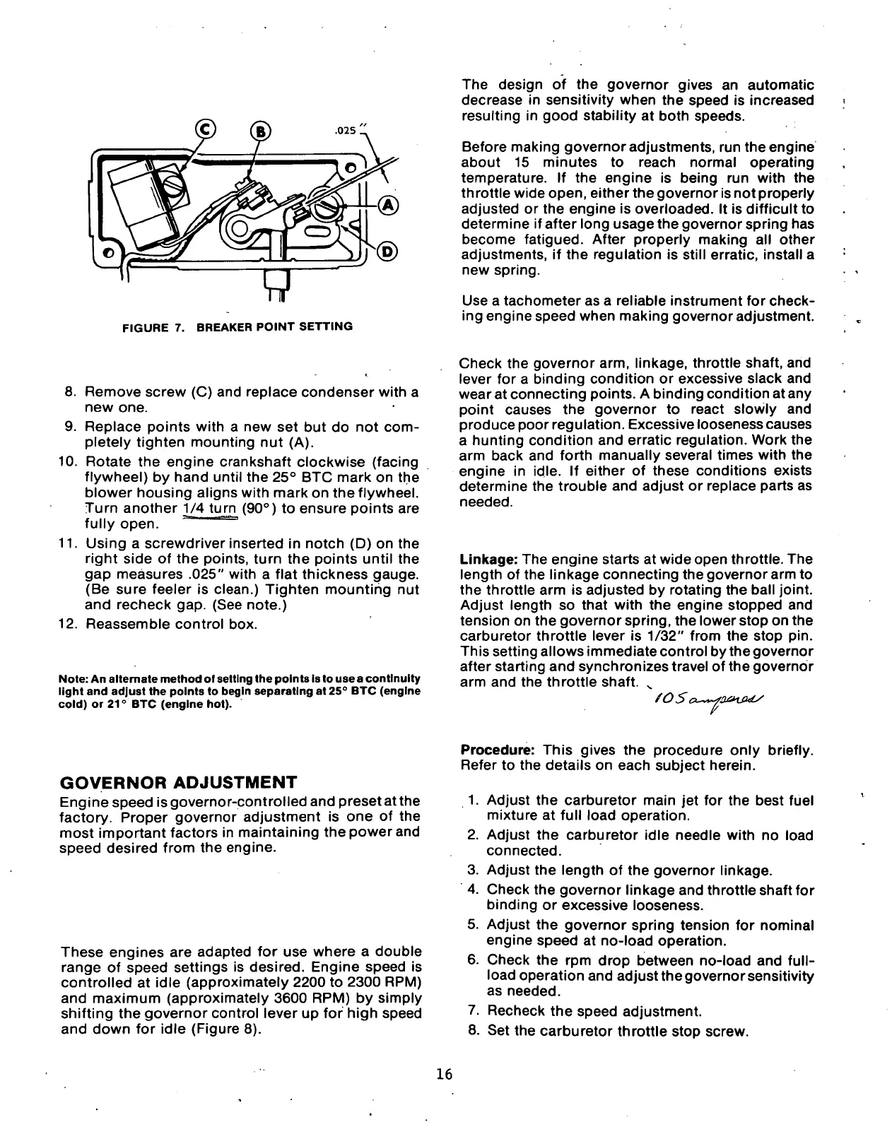
FIGURE 7. BREAKER POINT SETTING
The design of the governor gives an automatic
decrease in sensitivity when the speed is increased
resulting in good stability at both speeds.
Before making governor adjustments, run theengine
about 15 minutes to reach normal operating
temperature. If the engine is being run with the
th rottle wide open, either the governor is not properly
adjusted or the engine is overloaded. It is difficult to
determine if after long usage the governor spring has
become fatigued. After properly making all other
adjustments, if the regulation is still erratic, install a
new spring.
Use a tachometer as a reliable instrument for check-
ing engine speed when making governor adjustment.
8. Remove screw (C) and replace condenser with a
new one.
9. Replace points with a new set but do not com-
pletely tighten mounting nut (A).
10.
Rotate the engine crankshaft clockwise (facing
flywheel) by hand until the 25° BTC mark on the
blower housing aligns with mark on the flywheel.
Turn another 1/4 turn (90°) to ensure points are
fully open. "
11.
Using a screwdriver inserted in notch (D) on the
right side of the points, turn the points until the
gap measures .025" with a flat thickness gauge.
(Be sure feeler is clean.) Tighten mounting nut
and recheck gap. (See note.)
12.
Reassemble control box.
Note:
An altemate method of setting the points is to use a continuity
light and adjust the points to begin separating at 25° BTC (engine
cold) or 21° BTC (engine hot).
Check the governor arm, linkage, throttle shaft, and
lever for a binding condition or excessive slack and
wear at connecting points. A binding condition at any
point causes the governor to react slowly and
produce poor regulation. Excessive looseness causes
a hunting condition and erratic regulation. Work the
arm back and forth manually several times with the
engine in idle. If either of these conditions exists
determine the trouble and adjust or replace parts as
needed.
Linkage: The engine starts at wide open throttle. The
length of the linkage connecting the governor arm to
the throttle arm is adjusted by rotating the ball joint.
Adjust length so that with the engine stopped and
tension on the governor spring, the lower stop on the
carburetor throttle lever is 1/32" from the stop pin.
This setting allows immediate control by thegovernor
after starting and synchronizes travel of the governor
arm and the throttle shaft.
GOVERNOR
ADJUSTMENT
Engine speed is governor-controlled and preset at the
factory. Proper governor adjustment is one of the
most important factors in maintaining the power and
speed desired from the engine.
These engines are adapted for use where a double
range of speed settings is desired. Engine speed is
controlled at idle (approximately 2200 to 2300 RPM)
and maximum (approximately 3600 RPM) by simply
shifting the governor control lever up for high speed
and down for idle (Figure 8).
Procedure: This gives the procedure only briefly.
Refer to the details on each subject herein.
1.
Adjust the carburetor main jet for the best fuel
mixture at full load operation.
2.
Adjust the carburetor idle needle with no load
connected.
3. Adjust the length of the governor linkage.
4.
Check the governor linkage and throttle shaft for
binding or excessive looseness.
5. Adjust the governor spring tension for nominal
engine speed at no-load operation.
6. Check the rpm drop between no-load and
full-
load operation and adjust the governor sensitivity
as needed.
7. Recheck the speed adjustment.
8. Set the carburetor throttle stop screw.
16
 Loading...
