ENGINE
DISASSEMBLY
VALVE
SYSTEM
Properly seated valves are essential to good engine
performance. The aluminum cylinder heads are
removable for valve servicing. Do not use a pry to
loosen the cylinder
head;
rap sharply on the edge with
a soft faced hammer, taking care not to break any
cooling fins. A conventional type valve spring lifter
may be used when removing the valve spring locks,
which are of the split type. Clean all carbon deposits
from the cylinder heads, piston tops, valves, guides,
etc. If a valve face is burned or warped, or the stem
worn,
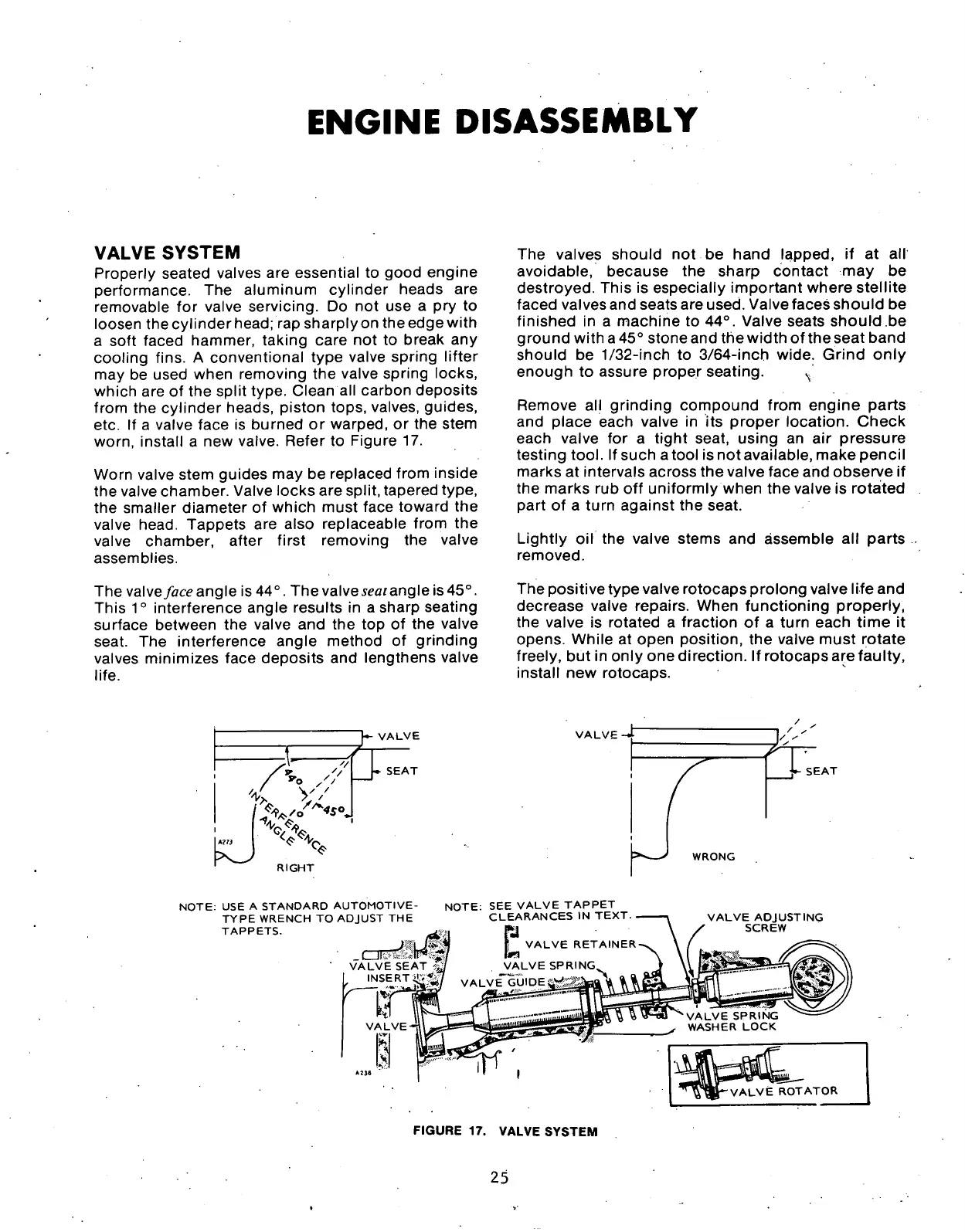
install a new valve. Refer to Figure 17.
Worn valve stem guides may be replaced from inside
the valve chamber. Valve locks are split, tapered type,
the smaller diameter of which must face toward the
valve head. Tappets are also replaceable from the
valve chamber, after first removing the valve
assemblies.
The valves should not be hand lapped, if at all
avoidable, because the sharp contact may be
destroyed.
This is especially important where stellite
faced valves and seats are used. Valve faces should be
finished in a machine to 44°. Valve seats should be
ground with a 45° stone and the width ofthe seat band
should be
1/32-inch
to 3/64-inch wide. Grind only
enough to assure proper seating.
N
Remove all grinding compound from engine parts
and place each valve in its proper location. Check
each valve for a tight seat, using an air pressure
testing
tool.
If such a tool is not available, make pencil
marks at intervals across the valve face and observe if
the marks rub off uniformly when the valve is rotated
part of a turn against the seat.
Lightly oil the valve stems and assemble all parts
removed.
The valve face angle is 44°. The valve
seat
angle is 45°.
This 1° interference angle results in a sharp seating
surface between the valve and the top of the valve
seat. The interference angle method of grinding
valves minimizes face deposits and lengthens valve
life.
The positive type valve rotocaps prolong valve life and
decrease valve repairs. When functioning properly,
the valve is rotated a fraction of a turn each time it
opens. While at open position, the valve must rotate
freely, but in only one direction. If rotocaps are faulty,
install new rotocaps.
VALVE
</ V''
RIGHT
» SEAT
VALVE-
V SEAT
WRONG
NOTE:
USE A STANDARD AUTOMOTIVE-
TYPE WRENCH TO ADJUST THE
TAPPETS.
NOTE:
SEE VALVE TAPPET
CLEARANCES IN TEXT.
VALVE RETAINER-
VALVE SPRING^
VALVE ADJUSTING
SCREW
FIGURE 17. VALVE SYSTEM
25
 Loading...
