Tappet Adjustment: The engine is equipped with
adjustable valve tappets. The valve tappet clearance
should be checked and adjusted at least every 400
operating hours or when poor engine performance is
noticed.
Adjust the valve clearance only when engine
is at ambient temperature. Proceed as follows:
1.
Remove all parts necessary to gain access to
valve tappets.
2.
Remove spark plugs to ease the task of turning
the engine crankshaft over by hand.
3. Use the engine flywheel to turn the crankshaft
over slowly by hand until the left hand intake valve
opens and closes. Continue turning the flywheel
until the TC mark is on the top and lined up with
the TC mark on the gear cover. Both valves should
be closed. This should place the left hand piston
at the top of its compression stroke, the position it
must be in to get proper valve adjustment forthe
left cylinder.
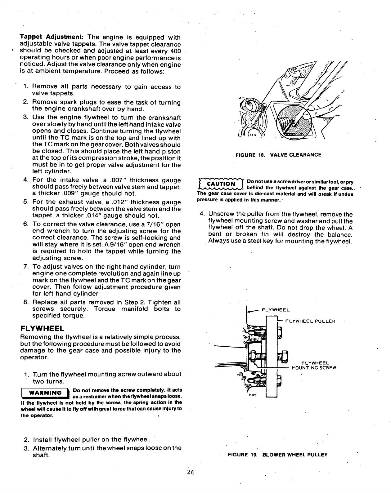
4.
For the intake valve, a .007" thickness gauge
should pass freely between valve stem and tappet,
a thicker .009" gauge should not.
5. For the exhaust valve, a .012" thickness gauge
should pass freely between the valve stem and the
tappet, a thicker .014" gauge should not.
6. To correct the valve clearance, use a 7/16" open
end wrench to turn the adjusting screw for the
correct clearance. The screw is self-locking and
will stay where it is set. A 9/16" open end wrench
is required to hold the tappet while turning the
adjusting screw.
7. To adjust valves on the right hand cylinder, turn
engine one complete revolution and again line up
mark on the flywheel and the TC mark on the gear
cover. Then follow adjustment procedure given
for left hand cylinder.
8. Replace all parts removed in Step 2. Tighten all
screws securely. Torque manifold bolts to
specified torque.
FLYWHEEL
Removing the flywheel isa relatively simple process,
but thefollowing procedure must be followed to avoid
damage to the gear case and possible injury to the
operator.
1.
Turn the flywheel mounting screw outward about
two turns.
WARNING
Do not remove the screw completely. It acts
as a restrainer when the flywheel snaps loose.
If the flywheel is not held by the screw, the spring action in the
wheel will cause it to fly off with great force that can cause injury to
the operator.
FIGURE 18. VALVE CLEARANCE
CAUTION
fc
w—w-*. /'w'S. S\ ^^J
Do not use a screwdriver or similar
tool,
or pry
behind the flywheel against the gear case.
•
The gear case cover is die-cast material and will break if undue
pressure is applied in this manner.
4.
Unscrew the puller from the flywheel, remove the
flywheel mounting screw and washer and pull the
flywheel off the shaft. Do not drop the wheel. A
bent or broken fin will destroy the balance.
Always use a steel key for mounting the flywheel.
FLYWHEEL
FLYWHEEL PULLER
FLYWHEEL
MOUNTING SCREW
2.
Install flywheel puller on the flywheel.
3. Alternately turn until the wheel snaps loose on the
shaft.
FIGURE 19. BLOWER WHEEL PULLEY
26
 Loading...
