3. Rotate the crank about 30 degrees from bottom
dead center and reinstall the bearing cap; tighten
the bolts to the torque specified in Assembly
Torques. Do not turn the crankshaft.
4.
Remove the bearing cap. Leave the flattened
Plastigauge on the part to which it has adhered
and compare the widest point with the
graduations on the Plastigauge envelope to
determine bearing clearance/.
OIL
SEALS
(Figure 36)
The bearing plate must be removed to replace the oil
seal.
Drive the oil seal out from the inside.
Before installing the seals, fill the space between lips
with a multi-purpose grease. This will improve
seal-
ing.-
When installing the gear cover oil
seal,
tap the seal
inward until it is 31/32" from the mounting face ofthe
cover.
When installing the bearing plate oil
seal,
tap the seal
into the bearing plate bore to bottom against the
shoulder in the plate bore. Use a seal expander or
place a piece of shim stock around the end of the
crankshaft, when replacing the bearing plate to avoid
damaging the
seal.
Remove the shim stock as soon as
the plate is in place.
HEAVIEST COMPRESSION
RING IN TOP GROOVE
COMPRESSION RINGS
OIL CONTROL RING
FIGURE 37. PISTON RINGS
3. Install the rings on the pistons starting with the oil
control ring (Figure 37). Use a piston ring
spreader to prevent twisting or excessive expan-
sion of the
ring.
Some oil control rings and all
compression rings have a dot or the word "top" on
one side of the ring to indicate which side faces
the top of the piston. Unmarked piston rings can
be installed either way. |f the oil control ring hasa
coil expander, install the expander first and then
close until the coil ends butt. The joint should be
180 degrees from the gap of that
ring.
INSTALLATION
OF PISTON IN
CYLINDER
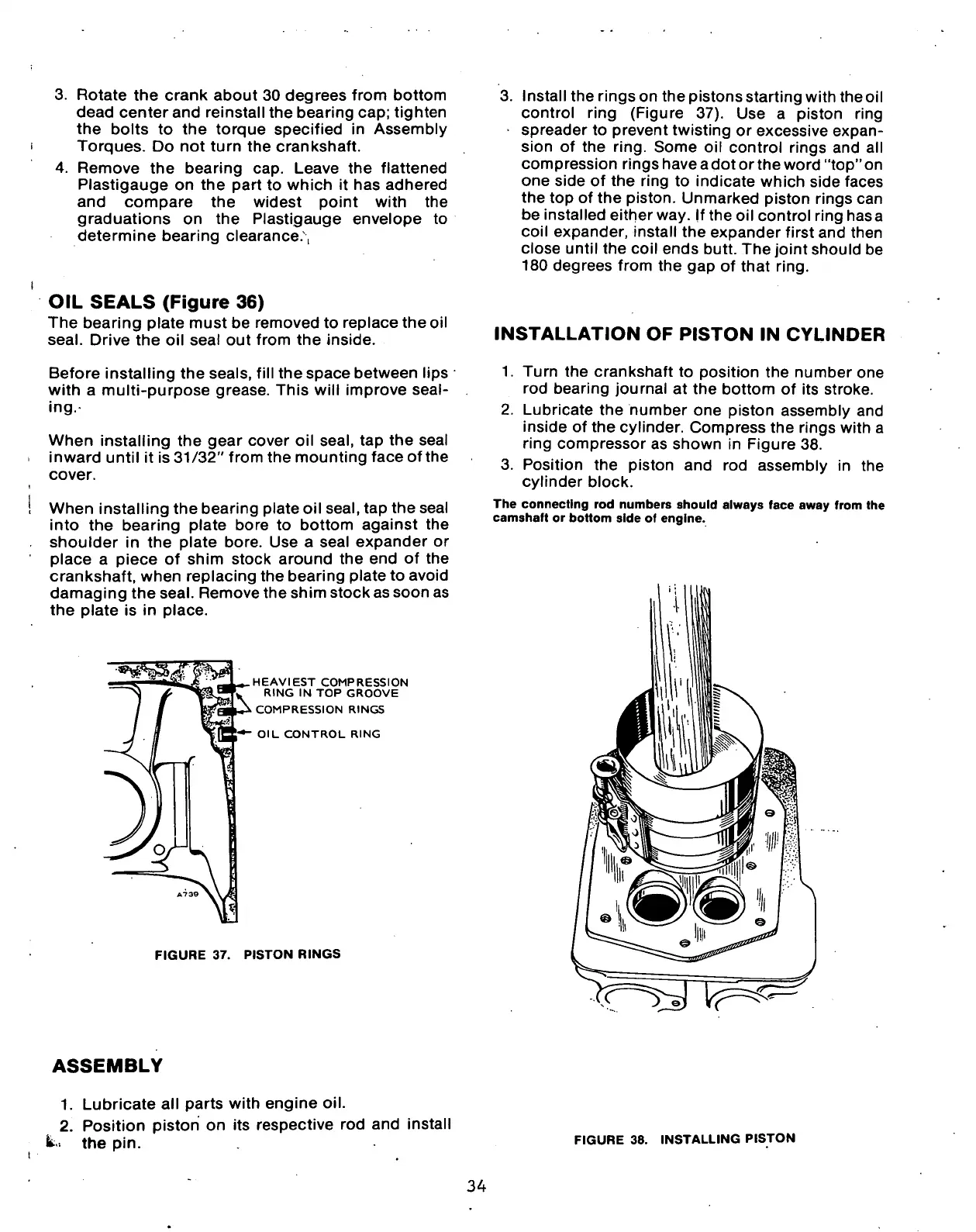
1.
Turn the crankshaft to position the number one
rod bearing joumal at the bottom of its stroke.
2.
Lubricate the humber one piston assembly and
inside of the cylinder. Compress the rings with a
ring compressor as shown in Figure 38.
3. Position the piston and rod assembly in the
cylinder block.
The connecting rod numbers should always face away from the
camshaft or bottom side of engine.
ASSEMBLY
1.
Lubricate all parts with engine oil.
2.
Position piston on its respective rod and install
fe- the pin.
FIGURE 38. INSTALLING PISTON
34
 Loading...
