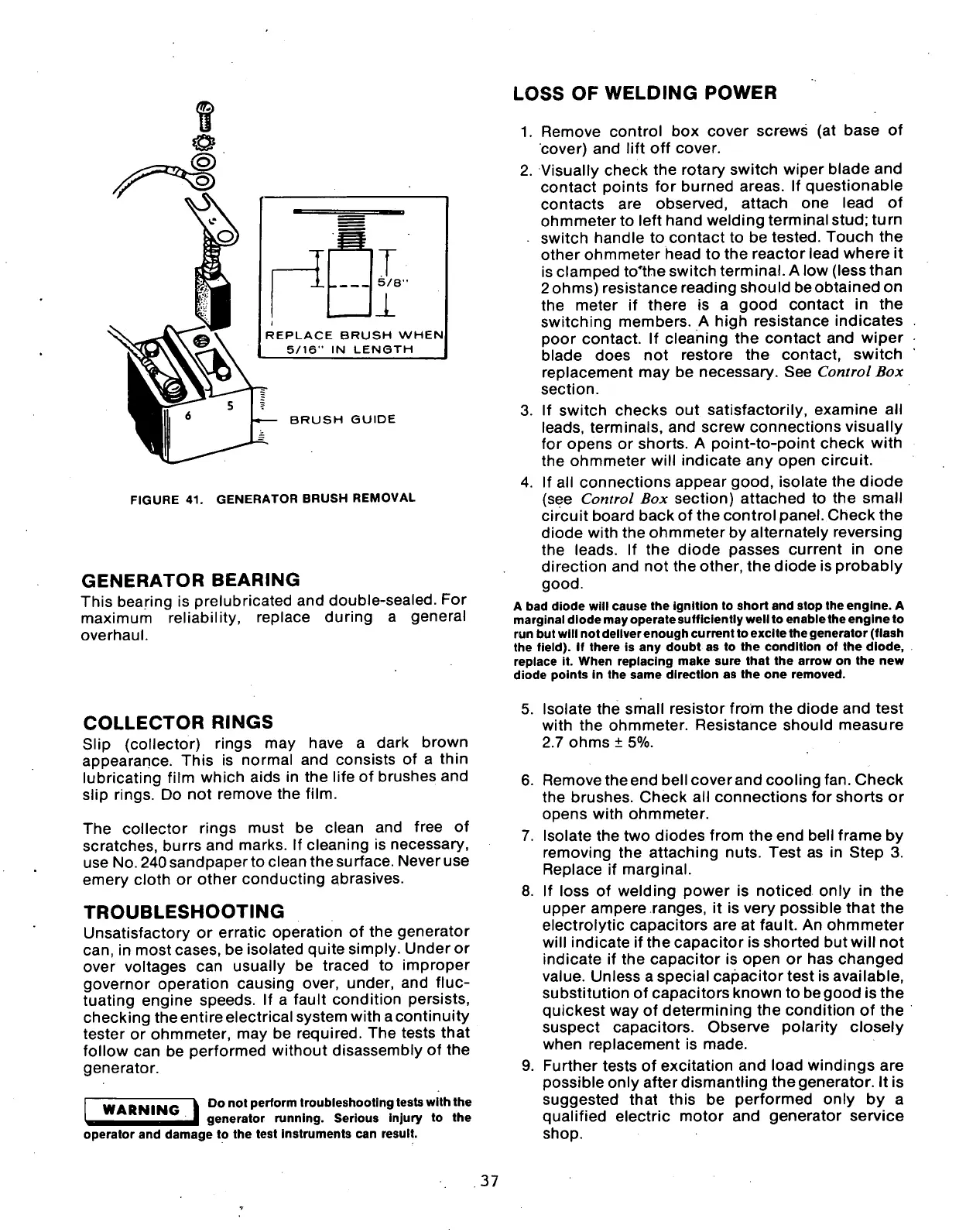
5/8"
REPLACE BRUSH WHEN
5/16" IN LENGTH
BRUSH GUIDE
FIGURE 41. GENERATOR BRUSH REMOVAL
GENERATOR
BEARING
This bearing is prelubricated and double-sealed. For
maximum reliability, replace during a general
overhaul.
LOSS
OF WELDING
POWER
1.
Remove control box cover screws (at base of
cover) and lift off cover.
2.
Visually check the rotary switch wiper blade and
contact points for burned areas. If questionable
contacts are observed, attach one lead of
ohmmeter to left hand welding terminal
stud;
turn
switch handle to contact to be tested. Touch the
other ohmmeter head to the reactor lead where it
is clamped to'the switch terminal. A low (less than
2ohms) resistance reading should beobtained on
the meter if there is a good contact in the
switching members. A high resistance indicates
poor contact. If cleaning the contact and wiper
blade does not restore the contact, switch
replacement may be necessary. See Control Box
section.
3. If switch checks out satisfactorily, examine all
leads,
terminals, and screw connections visually
for opens or shorts. A point-to-point check with
the ohmmeter will indicate any open circuit.
4.
If all connections appear good, isolate the diode
(see Control Box section) attached to the small
circuit board back of the control panel. Check the
diode with the ohmmeter by altemately reversing
the leads. If the diode passes current in one
direction and not the other, the diode is probably
good.
A bad diode will cause the ignition to short and stop the engine. A
marginal diode may operate sufficiently well to enable the engine to
run but will not deliver enough current to excite the generator (flash
the field). If there is any doubt as to the condition of the diode,
replace it. When replacing make sure that the arrow on the new
diode points in the same direction as the one removed.
COLLECTOR
RINGS
Slip (collector) rings may have a dark brown
appearance. This is normal and consists of a thin
lubricating film which aids in the life of brushes and
slip rings. Do not remove the
film.
The collector rings must be clean and free of
scratches, burrs and marks. If cleaning is necessary,
use No. 240 sandpaper to clean the surface. Never use
emery cloth or other conducting abrasives.
TROUBLESHOOTING
Unsatisfactory or erratic operation of the generator
can,
in most cases, be isolated quite simply. Under or
over voltages can usually be traced to improper
governor operation causing over, under, and fluc-
tuating engine speeds. If a fault condition persists,
checking the entire electrical system with a continuity
tester or ohmmeter, may be required. The tests that
follow can be performed without disassembly of the
generator.
WARNING
Do not perform troubleshooting tests with the
generator running. Serious injury to the
5. Isolate the small resistor from the diode and test
with the ohmmeter. Resistance should measure
2.7 ohms ± 5%.
6. Remove the end bell coverand cooling fan. Check
the brushes. Check all connections for shorts or
opens with ohmmeter.
7.
8.
9.
operator and damage to the test instruments can result.
Isolate the two diodes from the end bell frame by
removing the attaching nuts. Test as in Step 3.
Replace if marginal.
If loss of welding power is noticed only in the
upper ampere ranges, it is very possible that the
electrolytic capacitors are at fault. An ohmmeter
will indicate if the capacitor is shorted but will not
indicate if the capacitor is open or has changed
value.
Unless a special capacitor test is available,
substitution of capacitors known to be good is the
quickest way of determining the condition of the
suspect capacitors. Observe polarity closely
when replacement is made.
Further tests of excitation and load windings are
possible only after dismantling the generator. It is
suggested that this be performed only by a
qualified electric motor and generator service
shop.
37
 Loading...
